Section 7 Tasks
• Read the theory lesson below
• Read the ICND1 cram guide
IPv6 has been in development for several years and has actually been implemented on networks all over the world (in conjunciton with IPv4). Many network engineers have expressed their fear about having to learn a new addressing method, and I’ve even heard many say that they hope to retire before it becomes a requirement.
This fear, however, is unfounded. IPv6 is a user-friendly format, and once you become used to it, you will see that it is an improvement on IPv4 and you may actually come to prefer it. IPv6 is heavily tested in the CCNA exam; for this reason, you need to feel comfortable understanding how it works, as well as how to configure addresses, understand the standard, and apply IPv6 addresses to address network requirements.
Today you will learn about the following:
• History of IPv6
• IPv6 addressing format
• Implementing IPv6
• IPv6 subnetting
This module maps to the following CCNA syllabus requirements:
• Identify the appropriate IPv6 addressing scheme to satisfy addressing requirements in a LAN/WAN environment
• Describe IPv6 addresses
° Global Unicast
° Multicast
° Link-Local
° Unique-Local
° EUI 64
° Autoconfiguration
History of IPv6
Fit for Purpose?
When Sir Tim Berners-Lee devised the World Wide Web in 1989, there was no way he could have predicted the huge impact it was to have on the world. Personal computers were prohibitively expensive and there was no easy way to communicate over long distances unless you could afford expensive WAN connections. Even then, there was no agreed communication model for all to follow.
Something needed to change and change came in the form of a new addressing standard for IP. Learning from mistakes made and responding to changes in business requirements, the Internet Engineering Task Force (IETF) published the first of many IPv6 standards as far back as 1998.
There will be no switch-over date; instead, networks will gradually transition to running both IPv4 and IPv6, and then eventually IPv4 will be phased out of existence. At the moment, approximately 1% of all Internet traffic is running on IPv6 (source: Yves Poppe, IPv6 – A 2012 Report Card).
Why Migrate?
I’ve already said that when IPv4 was devised, the Internet wasn’t used by the general public, and why would they? There were no websites, no e-commerce, no mobile networks, and no social media. Even if you could afford a PC, there wasn’t much you could do with it. Now, of course, almost everybody is online. We carry out most of our day-to-day tasks using the Internet, and businesses rely on it to exist. Soon we will be using mobile devices to manage our cars and home security, to turn the coffee maker on, to set the heating level, and to set the TV to record our favourite show.
Some of this is already taking place, not only in Europe and the Americas but also in fastdeveloping countries such as India and China where billions of people live. IPv4 simply isn’t up to the job and even if it was, there aren ’t enough addresses to cater for demand.
Here are a few benefits to changing to IPv6:
• The simplified IPv6 Packet header
• Larger address space
• IPv6 addressing hierarchy
• IPv6 extensibility
• IPv6 broadcast elimination
• Stateless autoconfiguration
• Integrated mobility
• Integrated enhanced security
I’d like to delve into packet layer analysis of IPv6, as well as the many types of headers available, but there isn’t space here to do so, and since it isn’t tested in the exam there is no need to include it. Instead, I will focus on what you need to know for the exam and your role as a Cisco engineer.
Hex Numbering
It may be well worthwhile to have a short memory jogger on hex numbering.
You know that decimal numbers consist of 10 digits ranging from 0 to 9. Binary consists of two digits ranging from 0 to 1. Hex numbering ranges from 0 to F and has 16 digits. These addresses are also referred to as base 10, base 2, and base 16, respectively.
You can see that each numbering system starts with a zero, so:
Decimal – 0,1,2,3,4,5,6,7,8,9
Binary – 0,1
Hex – 0,1,2,3,4,5,6,7,8,9,A,B,C,D,E,F
When you write these addresses, you may not realise it but you are using columns from right to left; the rightmost is the one column and the next column is the base number times the preceding column, so:

You can see that each successive column from the right increases in value. For decimal numbering it is 10 multiplied by 1. For binary it is 1 and then 1 multiplied by the numbering system of 2. If you compare the three numbering systems up to the last hex digit, you can begin to see why hex is the preferred format for IPv6 addressing.
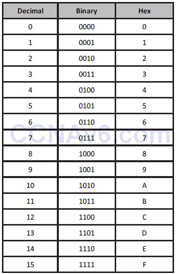
In order to provide enough addresses for our needs many years into the future, IPv6 has been designed to provide many trillions of available addresses. In order to do this, the numbering range has been expanded from 32 binary bits to 128 bits. Every 4 bits can be represented as one hex digit (as can be seen from the chart above). Logic then dictates that two hex digits will give us 8 bits, which is a single byte, or octet.
An IPv6 address is 128 bits in length and this is broken down into eight sets of 16 bits each separated by a colon when written in full format. Every 4 hex bits can range from 0000 to FFFF, with F being the highest digit available in hex numbering:

IPv6 Addressing
As we already know, IPv6 uses 128-bit addresses. Because the address format is different from the IPv4 address format that we are all accustomed to, it is often confusing at first glance. However, once understood, the logic and structure is all very simple. The 128-bit IPv6 addresses use hexadecimal values (i.e., numbers 0 through 9 and letters A through F). While in IPv4 the subnet mask can be represented in either CIDR notation (e.g., /16 or /32) or in dotted-decimal notation (e.g., 255.255.0.0 or 255.255.255.255), IPv6 subnet masks are represented only in CIDR notation due to the length of the IPv6 address. Global 128-bit IPv6 addresses are divided into the following three sections:
• The provider-assigned prefix
• The site prefix
• The interface or host ID
The provider-assigned prefix, which is also referred to as the global address space, is a 48-bit prefix that is divided into the following three distinct parts:
• The 16-bit reserved IPv6 global prefix
• The 16-bit provider-owned prefix
• The 16-bit provider-assigned prefix
The IPv6 global prefix is used to represent the IPv6 global address space. All IPv6 global Internet addresses fall within the 2000::/16 to 3FFF::/16 range. The 16-bit provider-owned IPv6 prefix is assigned to and owned by the provider. The assignment of these prefixes follows the same rules as prefix assignment in IPv4. The provider-owned prefix falls within the 0000::/32 to FFFF::/32 range.
The next 16-bits represent an IPv6 prefix assigned to an organisation by the actual provider from within the provider-assigned prefix address space. This prefix falls within the 0000::/48 to FFFF::/48 range. Collectively, these first 48-bits are referred to as the provider-assigned prefix, which is illustrated in Figure 7.1 below:
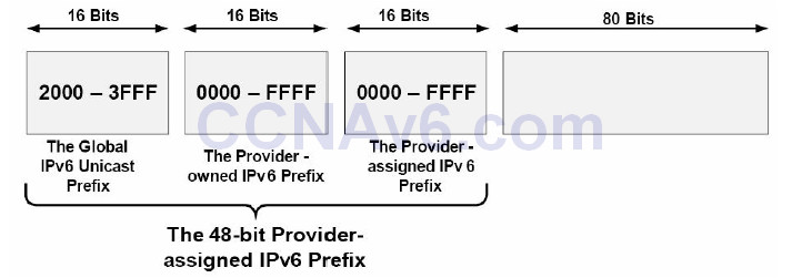
Figure 7.1 – The 48-bit Provider-Assigned IPv6 Prefix
The site prefix is the next 16 bits following the 48-bit provider-assigned prefix. The subnet mask length for a site prefix is /64, which includes the 48-bit provider-assigned prefix. This prefix length allows for 264 addresses within each site prefix. Figure 7.2 below illustrates the 16-bit site prefix:

Figure 7.2 – The 16-bit IPv6 Site Prefix
Following the site prefix, the next 64 bits are used for interface or host addressing. The interface or host ID portion of an IPv6 address represents the network device or host on the IPv6 subnet. The different ways in which the interface or host address is determined will be described in detail later in this module. Figure 7.3 below illustrates how IPv6 prefixes are assigned:
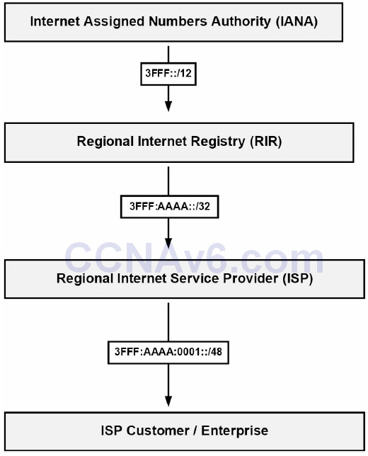
Figure 7.3 – Assigning IPv6 Prefixes
Referencing Figure 7.3, once customers have been assigned the /48 prefix by the ISP, they are then free to assign and use whatever site prefixes and host or interface addresses they want within that 48-bit provider-assigned prefix. The sheer amount of address space available makes it impossible for any single enterprise customer to require more than a single provider-assigned prefix, while still allowing all devices within the enterprise network to be allocated a unique IPv6 global address. NAT, therefore, will never be required for IPv6.
IPv6 Address Representation
The three ways in which IPv6 addresses can be represented are as follows:
• The preferred or complete address representation or form
• Compressed representation
• IPv6 addresses with an embedded IPv4 address
While the preferred form or representation is the most commonly used method for representing the 128-bit IPv6 address in text format, it is also important to be familiar with the other two methods of IPv6 address representation. These methods are described in the following sections.
The Preferred Form
The preferred representation for an IPv6 address is the longest format, also referred to as the complete form of an IPv6 address. This format represents all 32 hexadecimal characters that are used to form an IPv6 address. This is performed by writing the address as a series of eight 16- bit hexadecimal fields, separated by a colon (e.g., 3FFF:1234:ABCD:5678:020C:CEFF:FEA7:F3A0).
Each 16-bit field is represented by four hexadecimal characters and each character represents 4 bits. Each 16-bit hexadecimal field can have a value of between 0x0000 and 0xFFFF, although, as will be described later in this module, different values have been reserved for use in the first 16 bits, so all possible values are not used. When writing IPv6 addresses, hexadecimal characters are not case sensitive. In other words, 2001:ABCD:0000 and 2001:abcd:0000 are the exact same thing. The complete form for IPv6 address representation is illustrated in Figure 7.4 below:

Figure 7.4 – The Preferred Form for IPv6 Address Representation
The following IPv6 addresses are examples of valid IPv6 addresses in the preferred form:
• 0000:0000:0000:0000:0000:0000:0000:0001
• 2001:0000:0000:1234:0000:5678:af23:bcd5
• 3FFF:0000:0000:1010:1A2B:5000:0B00:DE0F
• fec0:2004:ab10:00cd:1234:0000:0000:6789
• 0000:0000:0000:0000:0000:0000:0000:0000
Compressed Representation
Compressed representation allows for IPv6 addresses to be compressed in one of two ways. The first method allows a double colon (::) to be used to compress consecutive zero values in a valid IPv6 address for successive 16-bit fields comprised of zeros or for leading zeros in the IPv6 address. When using this method, it is important to remember that the double colon can be used only once in an IPv6 address.
When the compressed format is used, each node and router is responsible for counting the number of bits on either side of the double colon to determine the exact number of zeros it represents. Table 7.1 below shows IPv6 addresses in the preferred form and the compressed representation of those addresses:
Table 7.1 – Complete IPv6 Addresses in the Preferred Compressed Form

As previously stated, the double colon cannot be used more than once in a single IPv6 address. If, for example, you wanted to represent the complete IPv6 address for 2001:0000:0000:1234:0000:0000:af23:bcd5 in compressed form, you could use the double colon only once, even though there are two consecutive strings of zeros within the address. Therefore, attempting to compress the address to 2001::1234::af23:bcd5 would be considered illegal; however, the same IPv6 address could be compressed to either 2001::1234:0000:0000:af23:bcd5 or 2001:0000:0000:1234::af23:bcd5, depending upon preference.
The second method of IPv6 compressed address representation is applicable to each 16-bit field and allows leading zeros to be omitted from the IPv6 address. When using this method, if every bit in the 16-bit field is set to 0, then one zero must be used to represent this field. In this case, not all of the zero values can be omitted. Table 7.2 below shows IPv6 addresses in the preferred form and how they can be compressed using the second method of IPv6 compressed form representation.
Table 7.2 – Complete IPv6 Addresses in the Alternative Compressed Form

While there are two methods of representing the complete IPv6 address in compressed form, it is important to remember that both methods are not mutually exclusive. In other words, these methods can be used at the same time to represent the same IPv6 address. This is commonly used when the complete IPv6 address contains both consecutive strings of zeros and leading zeros in other fields within the address. Table 7.3 below shows IPv6 addresses in the complete form that include both consecutive strings of zeros and leading zeros, and how these addresses are represented in the compressed form:
Table 7.3 –Complete IPv6 Addresses Using Both Compressed Form Methods

IPv6 Addresses with an Embedded IPv4 Address
The third representation of an IPv6 address is to use an embedded IPv4 address within the IPv6 address. While valid, it is important to keep in mind that this method is being deprecated and is considered obsolete because it is applicable only in the transition of IPv4 to IPv6.
The Different IPv6 Address Types
IPv4 supports four different classes of addresses, which are Anycast, Broadcast, Multicast, and Unicast. While the term Anycast has not been used in previous modules in this guide, it is important to remember that Anycast addresses are not special types of addresses. Instead, an Anycast address is simply an IP address that is assigned to multiple interfaces. Common examples of technologies that use Anycast addressing include IP Multicast implementations and 6to4 relay implementation.
NOTE: 6to4 is a transition mechanism for migrating from IPv4 to IPv6. For the CCNA exam, you only need to know that it exists.
With Anycast addressing, devices use the common address that is closest to them based on the routing protocol metric. The next closest address is then used in the event that the primary address is no longer reachable. This concept is illustrated in Figure 7.5 below:
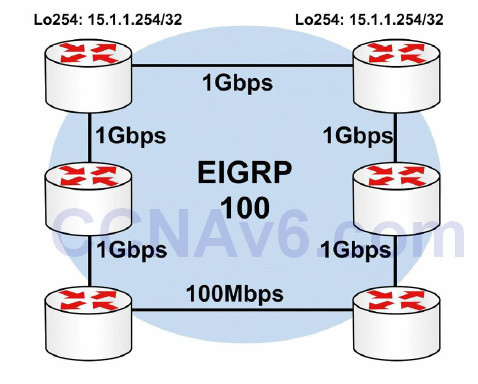
Figure 7.5 – Understanding Anycast Addressing
Referencing Figure 7.5, both R1 and R2 have a Loopback 254 interface that is configured using a common address: 15.1.1.254/32. This prefix is then advertised dynamically via EIGRP. By default, both R1 and R2 will prefer the 15.1.1.254/32 prefix via their respective Loopback interfaces, as that is a directly connected subnet. Therefore, the common address used will never result in a conflict on either router.
Assuming normal EIGRP metric calculation, R3 and R5 will prefer the Anycast address advertised by R1 due to the lower IGP metric. Similarly, R4 and R6 will prefer the Anycast address advertised by R2 due to the lower IGP metric. In the event that either R1 or R2 fails, the remaining routers in the network will use the Anycast address advertised by the remaining router. When using Anycast addressing, organisations can use a Unicast address either in the RFC 1918 address space or within their public block.
NOTE: You are not expected to implement any Anycast addressing or solutions in the current CCNA exam. However, it is important to be familiar with the concept. It will make more sense after you have reviewed the routing chapters.
At this level, IPv4 Broadcast, Multicast, and Unicast addresses require no further explanation and will not be described in any additional detail in this module or in the remainder of this guide. While IPv4 supports these four different types of addresses, IPv6 does away with the Broadcast addresses and instead supports only the following types of addresses:
• Link-Local addresses
• Site-Local addresses
• Aggregate Global Unicast addresses
• Multicast addresses
• Anycast addresses
• Loopback addresses
• Unspecified addresses
Link-Local Addresses
IPv6 Link-Local addresses can be used only on the local link (i.e., a shared segment between devices), and are automatically assigned to each interface when IPv6 is enabled on that interface. These addresses are assigned from the Link-Local prefix FE80::/10. Keep in mind that FE80::/10 is the equivalent of FE80:0:0:0:0:0:0:0/10, which can also be represented as FE80:0000:0000:0000:0000:0000:0000:0000/10. To complete the address, bits 11 through 64 are set to 0 and the interface Extended Unique Identifier 64 (EUI-64) is appended to the Link-Local address as the low-order 64 bits. The EUI-64 is comprised of the 24-bit manufacturer ID assigned by the IEEE and the 40-bit value assigned by that manufacturer to its products. EUI-64 addressing is described in greater detail later in this module. The format for a Link-Local address is illustrated in Figure 7.6 below:

Figure 7.6 – IPv6 Link-Local Addressing
Link-local addresses are unique in that they do not change once assigned to an interface. This means that if an interface is assigned a public IPv6 address (e.g., 2001:1000::1/64) and the public IPv6 prefix was changed (i.e., 2001:2000::1/64), the Link-Local address would not change. This allows the host or router to remain reachable by its neighbour, while IPv6 global Internet addresses change. IPv6 routers should not forward packets that have Link-Local source or destination addresses to other IPv6 routers.
Site-Local Addresses
Site-Local addresses are Unicast addresses that are used only within a site. Unlike Link-Local addresses, Site-Local addresses must be configured manually on network devices. These addresses are the IPv6 equivalent of the private IPv4 address space defined in RFC 1918 and can be used by organisations that do not have globally routable IPv6 address space. These addresses are not routable on the IPv6 Internet.
While it is possible to perform NAT for IPv6, it is not recommended; hence, the reason for the much larger IPv6 addresses. Site-Local addresses are comprised of the FEC0::/10 prefix, a 54-bit subnet ID, and an interface identifier in the EUI-64 format used by Link-Local addresses. While the 54 bits in a Link-Local address are set to a value of 0, the same 54 bits in Site-Local addresses are used to create different IPv6 prefixes (up to 254). The format for the Site-Local address is illustrated in Figure 7.7 below:

Figure 7.7 – IPv6 Site-Local Addressing
While IPv6 Site-Local addresses are described in this section and are still supported in Cisco IOS software, it is important to know that these addresses are deprecated by RFC 3879 (Deprecating Site Local Addresses). Moreover, RFC 4193 (Unique Local IPv6 Unicast Addresses) describes Unique-Local addresses (ULAs), which serve the same function as Site-Local addresses but they are not routable on the IPv6 global Internet, only within a site.
Unique-Local addresses are assigned from the FC00::/7 IPv6 address block, which is then further divided into two /8 address groups referred to as the assigned and random groups. These two groups are the FC00::/8 and the FD00::/8 IPv6 address blocks. The FC00::/8 block is managed by an allocation authority for /48s in use, while the FD00::/8 block is formed by appending a randomly generated 40-bit string to derive a valid /48 block.
Aggregate Global Unicast Addresses
Aggregate Global Unicast addresses are the IPv6 addresses used for generic IPv6 traffic, as well as for the IPv6 Internet. These are similar to the public addresses used in IPv4. From a network addressing point of view, each IPv6 Global Unicast address is comprised of three main sections: the prefix received from the provider (48 bits in length), the site prefix (16 bits in length), and the host portion (64 bits in length). This makes up the 128-bit address used in IPv6.
As we learned earlier in this module, the provider-assigned prefix is assigned to an organisation by an IPv6 provider. By default, these prefixes use /48 prefix lengths. In addition, these prefixes are assigned from the IPv6 address spaces (i.e., the /32 prefix lengths) that are owned by the provider. Each provider will own its own IPv6 address space, and the IPv6 prefix assigned by one provider cannot be used on the network of another provider.
Within a site, administrators can then subnet the provider-assigned 48-bit prefix into 64-bit site prefixes by using bits 49 through 64 for subnetting, allowing for 65,535 different subnets for use within their network. The host portion of an IPv6 address represents the network device or host on the IPv6 subnet. This is represented by the low-order 64 bits of the IPv6 address.
Aggregate Global Unicast addresses for IPv6 are assigned by the Internet Assigned Numbers Authority (IANA) and fall within the IPv6 prefix 2000::/3. This allows for a range of Aggregate Global Unicast addresses from 2000 to 3FFF, as illustrated in Table 7.4 below:
Table 7.4 – IPv6 Aggregate Global Unicast Addresses

From the 2000::/3 IPv6 block, only three subnets have been allocated for use at the time this module was written. These allocations are illustrated in Table 7.5 below:
Table 7.5 – Assigned IPv6 Aggregate Global Unicast Addresses

NOTE: The 6to4 transition addresses and the 6bone prefix are described later in this guide.
Within the range of IPv6 Global Aggregate Unicast addresses, a special experimental range is reserved called ORCHID (an acronym for Overlay Routable Cryptographic Hash Identifiers defined in RFC 4843). ORCHID addresses are non-routed IPv6 addresses used for cryptographic hash identifiers. These addresses use the IPv6 prefix 2001:10::/28. Going into detail on ORCHID addresses is beyond the scope of the current CCNA exam requirements and will not be included in this module or in the remainder of this guide.
Multicast Addresses
The Multicast addresses used in IPv6 are derived from the FF00::/8 IPv6 prefix. In IPv6, Multicast operates in a different manner than that of Multicast in IPv4. IP Multicast is used extensively in IPv6 and replaces IPv4 protocols, such as the Address Resolution Protocol (ARP). In addition, Multicast is used in IPv6 for prefix advertisements and renumbering, as well as for Duplicate Address Detection (DAD). These concepts are all described later in this module.
Multicast packets in IPv6 do not use the TTL value to restrict such packets to the local network segment. Instead, the scoping is defined within the Multicast address itself via the use of the Scope field. IPv6 nodes on a network segment listen to Multicast and may even send Multicast packets to exchange information. This allows all nodes on an IPv6 segment to know about all the other neighbours on that same segment. The format for Multicast addresses used in IPv6 networks is illustrated in Figure 7.8 below:

Figure 7.8 – IPv6 Multicast Addressing
As illustrated in Figure 7.8, the format of the IPv6 Multicast address is slightly different from the formats of the other IPv6 addresses you have learned about up until this point. The first 8 bits of the IPv6 Multicast address represent the Multicast prefix FF::/8. The Flag field in the IPv6 Multicast address is used to indicate the type of Multicast address, either permanent or temporary.
Permanent IPv6 Multicast addresses are assigned by IANA, while temporary IPv6 Multicast addresses can be used in pre-deployment Multicast testing. The Flag field may contain one of the two possible values illustrated in Table 7.6 below:
Table 7.6 – IPv6 Permanent and Temporary Multicast Addresses

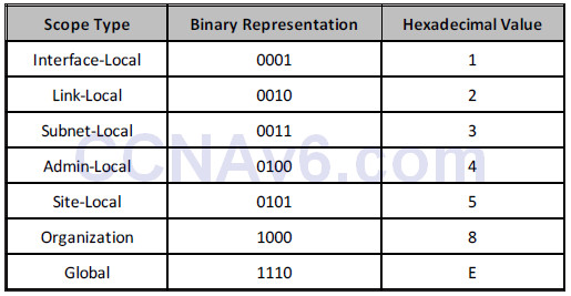
The next 4 bits in the Multicast address represent the scope. In IPv6 Multicasting, this field is a mandatory field that restricts Multicast packets from being sent to other areas in the network. This field essentially provides the same function as the TTL field that is used in IPv4. However, with IPv6, there are several types of scopes, which are listed in Table 7.7 below:
Table 7.7 – IPv6 Multicast Address Scopes
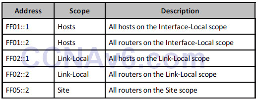
Within the IPv6 Multicast prefix, certain addresses are reserved. These reserved addresses are referred to as Multicast Assigned addresses, which are presented in Table 7.8 below:
Table 7.8 – IPv6 Reserved Multicast Addresses
In addition to these addresses, a Solicited-Node Multicast address is enabled automatically for each Unicast and Anycast address configured on a router interface or network host. This address has a Link-Local scope, which means that it will never traverse farther than the local network segment. Solicited-Node Multicast addresses are used for the following two reasons: the replacement of IPv4 ARP and DAD.
Because IPv6 does not use ARP, Solicited-Node Multicast addresses are used by network hosts and routers to learn the Data Link addresses of neighbouring devices. This allows for the conversion and sending of IPv6 packets to IPv6 hosts and routers as frames. DAD is part of the IPv6 Neighbor Discovery Protocol (NDP), which will be described in detail later in this module. DAD simply allows a device to validate whether an IPv6 address is already in use on the local segment before it configures the address as its own using autoconfiguration. In essence, it provides a similar function to Gratuitous ARP used in IPv4. Solicited-Node Multicast addresses are defined by the IPv6 prefix FF02::1:FF00:0000/104. These addresses are comprised of the FF02::1:FF00:0000/104 prefix in conjunction with the low-order 24 bits of the Unicast or Anycast address. Figure 7.9 below illustrates the format of these IPv6 addresses:

Figure 7.9 – IPv6 Solicited-Node Multicast Addresses
In a manner similar to IPv4 Multicast mapping for Ethernet, IPv6 also uses a unique means to map Layer 3 IPv6 Multicast addresses to Layer 2 Multicast addresses. Multicast mapping in IPv6 is enabled by appending the low-order 32 bits of a Multicast address to the 16-bit prefix 33:33, which is the defined Multicast Ethernet prefix for IPv6 networks. This is illustrated in Figure 7.10 below for all the routers on the Interface-Local scope prefix FF02::2:
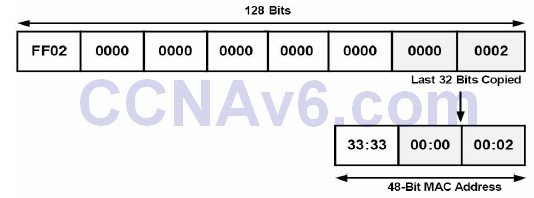
Figure 7.10 – IPv6 Multicast Addresses
Anycast Addresses
Anycast, which was introduced earlier in this section, can be described simply as one-to-nearest communication, because the nearest common address, based on routing protocol metrics, will always be preferred by the local device. In IPv6 there is no specially allocated range for Anycast, as Anycast addresses use Global Unicast, Site-Local, or even Link-Local addresses. However, there is an Anycast address reserved for special use. This special address is referred to as the Subnet-Router Anycast address and is formed with the subnet’s 64-bit Unicast prefix, with the remaining 64 bits set to zero (e.g., 2001:1a2b:1111:d7e5:0000:0000:000:0000). Anycast addresses must not be used as the source address of an IPv6 packet. These addresses are typically used by protocols such as Mobile IPv6, which is outside the scope of the CCNA.
Loopback Addresses
Loopback addresses in IPv6 are used in the same manner as in IPv4. Each device has one IPv6 Loopback address, which is comparable to the 127.0.0.1 Loopback address used in IPv4, and this address is used by the device itself. IPv6 Loopback addresses use the prefix ::1, which can be represented as 0000:0000:0000:0000:0000:0000:0000:0001 in the preferred address format. This means that in Loopback addresses, all bits are set to 0, except for the last bit, which is always set to 1. These addresses are always assigned automatically when IPv6 is enabled on a device and they can never be changed.
Unspecified Addresses
In IPv6 addressing, unspecified addresses are simply Unicast addresses that are not assigned to any interface. These addresses indicate the absence of an IPv6 address and are used for special purposes that include IPv6 DHCP and DAD. Unspecified addresses are represented by all 0 values in the IPv6 address and can be written using the :: prefix. In the preferred format, these addresses are represented as 0000:0000:0000:0000:0000:0000:0000:0000.
IPv6 Protocols and Mechanisms
While version 6 of the Internet Protocol is similar to version 4, there are significant differences in the operation of the former compared to the latter. The following IPv6 protocols and mechanisms are described in this section:
• ICMP for IPv6
• The IPv6 Neighbor Discovery Protocol (NDP)
• IPv6 stateful autoconfiguration
• IPv6 stateless autoconfiguration
ICMP for IPv6
ICMP is used to report errors and other information to the source hosts regarding the delivery of IP packets to the intended destination. ICMPv6, which is defined in RFC 2463 as protocol number 58, supports messages for ICMPv4 and includes additional messages for ICMPv6. ICMPv6 is used in the Next Header field of the basic IPv6 packet header. Unlike in IPv4, IPv6 views ICMPv6 as an upper-layer protocol, such as TCP, for example, which means that ICMPv6 is placed after all possible extension headers in the IPv6 packet. The fields that are contained within the ICMPv6 packet are illustrated in Figure 7.11 below:

Figure 7.11 – The ICMPv6 Packet Header
Within the ICMPv6 packet header, the 8-bit Type field is used to indicate or identify the type of ICMPv6 message. This field is used to provide both error and informational messages. Table 7.9 below lists and describes some common values that can be found within this field:
Table 7.9 – ICMPv6 Message Types
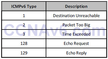
NOTE: These same message types are also used in ICMPv4.
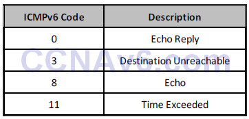
Following the Type field, the 8-bit Code field provides details pertaining to the type of message sent. Table 7.10 below illustrates common values for this field, which are also shared by ICMPv4:
Table 7.10 – ICMPv6 Codes
Following the Code field, the 16-bit Checksum field contains a computed value used to detect data corruption in ICMPv6. Finally, the Message or Data field is an optional, variable-length field that contains the data specific to the message type indicated by the Type and Code fields. When used, this field provides information to the destination host. ICMPv6 is a core component of IPv6. Within IPv6, ICMPv6 is used for the following:
• Duplicate Address Detection (DAD)
• The replacement of ARP
• IPv6 stateless autoconfiguration
• IPv6 prefix renumbering
• Path MTU Discovery (PMTUD)
NOTE: Of the options above, DAD and stateless autoconfiguration will be described later in this section. PMTUD is beyond the scope of the current CCNA exam requirements and will not be described in any additional detail in this module or in the remainder of this guide.
The IPv6 Neighbor Discovery Protocol (NDP)
The IPv6 NDP enables the plug-and-play features of IPv6. It is defined in RFC 2461 and is an integral part of IPv6. NDP operates in the Link Layer and is responsible for the discovery of other nodes on the link, determining the Link Layer addresses of other nodes, finding availablerouters, and maintaining reachability information about the paths to other active neighbour nodes. NDP performs functions for IPv6 similar to the way ARP (which it replaces) and ICMP Router Discovery and Router Redirect Protocols do for IPv4. However, it is important to remember that NDP provides greater functionality than the mechanisms used in IPv4. Used in conjunction with ICMPv6, NDP allows for the following:
• Dynamic neighbour and router discovery
• The replacement of ARP
• IPv6 stateless autoconfiguration
• Router redirection
• Host parameter discovery
• IPv6 address resolution
• Next-hop router determination
• Neighbor Unreachability Detection (NUD)
• Duplicate Address Detection (DAD)
NOTE: You are not required to delve into specifics on each of the advantages listed above.
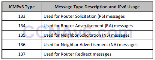
Neighbor Discovery Protocol defines five types of ICMPv6 packets, which are listed and described in Table 7.11 below:
Table 7.11 – ICMPv6 NDP Message Types
Router Solicitation messages are sent by hosts when interfaces are enabled for IPv6. These messages are used to request that routers on the local segment generate RA messages immediately, rather than at the next scheduled RA interval. Figure 7.12 below illustrates a wire capture of an RS message:

Figure 7.12 – IPv6 Router Solicitation Message
Upon receiving the RS message, routers advertise their presence using RA messages, which typically include prefix information for the local link as well as any additional configuration, such as suggested hop limits. The information contained within the RA is illustrated in Figure 7.13 below:
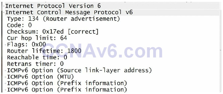
Figure 7.13 – IPv6 Router Advertisement Message
To reiterate, RS and RA messages are for router-to-host or host-to-router exchanges, as illustrated below:
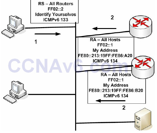
Figure 7.14 – IPv6 RS and RA Messages
IPv6 NS messages are Multicast by IPv6 routers on the local network segment and are used to determine the Data Link address of a neighbour or to verify that a neighbour is still reachable (thus replacing the ARP function). These messages are also used for Duplicate Address Detection. While delving into detail on NS messages is beyond the scope of the CCNA exam requirements, Figure 7.15 below illustrates a wire capture of an IPv6 Neighbor Solicitation message:

Figure 7.15 – IPv6 Neighbor Solicitation Message
Neighbor Advertisement messages are typically sent by routers on the local network segment in response to received NS messages. However, if, for example, an IPv6 prefix changes, then routers may also send out unsolicited NS messages advising other devices on the local network segment of the change. As is the case with NA messages, going into detail on the format or fields contained within the NA message is beyond the scope of the CCNA exam requirements. Figures 7.16 and 7.17 below illustrate a wire capture of the Neighbor Advertisement message, which is also sent via IPv6 Multicast:
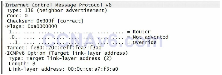
Figure 7.16 – IPv6 Neighbor Advertisement Message
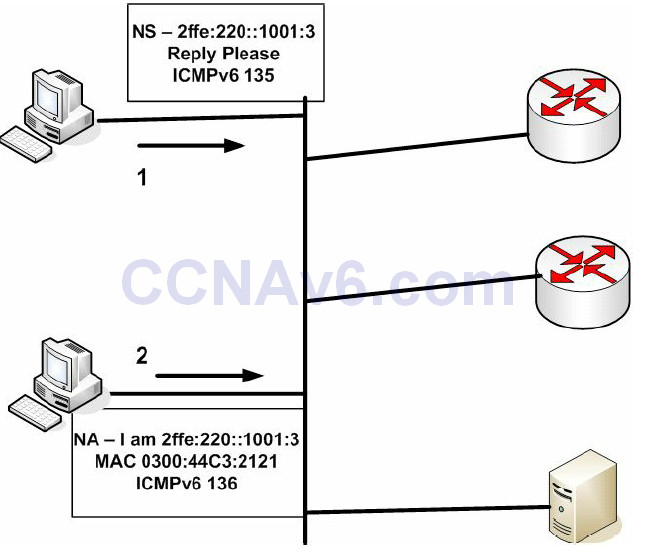
Figure 7.17 – IPv6 Neighbor Advertisement Messages
Finally, router redirection uses ICMPv6 Redirect messages, which are defined as message type 137. Router redirection is used to inform network hosts that a router with a better path to the intended destination exists on the network. It works in the same manner as it does for ICMPv4, which redirects traffic in current IPv4 networks.
IPv6 Stateful Autoconfiguration
As previously stated in this module, stateful autoconfiguration allows network hosts to receive their addressing information from a network server (e.g., via DHCP). This method of autoconfiguration is supported by both IPv4 and IPv6. In IPv6 networks, DHCPv6 is used to provide stateful (and stateless) autoconfiguration services for IPv6 hosts. In IPv6 implementations, when an IPv6 host receives RA messages from routers on the local network segment, the host examines these packets to determine whether DHCPv6 can be used. The RA messages provide this information by setting either the M (Managed) or the O (Other) bits to 1. With DHCP the client is configured to obtain information from the DHCP server. With DHCPv6, the client doesn’t know where the information comes from, which could be from SLAAC, stateful DHCPv6, or a combination of both.
The M bit in Router Advertisement messages is the Managed Address Configuration Flag bit. When this bit is set (i.e., it contains a value of 1), it instructs the IPv6 host to obtain a stateful address, which is provided by DHCPv6 servers. The O bit in Router Advertisement messages is the Other Stateful Configuration Flag bit. When this bit is set (i.e., it contains a value of 1), it instructs the IPv6 host to use DHCPv6 to obtain more configuration settings, such as DNS and WINS servers, for example.
If a host has not been configured with an IPv6 address, it can use one of three methods to obtain one, as well as other network settings such as the DNS server address:
• SLACC – Stateless Autoconfiguration M and O bits set to 0 means that there is no DHCPv6 information. The host receives all necessary information from an RA.
• Stateful DHCPv6 – M flag set to 1 tells the host to use DHCPv6 for all address and network information.
• Stateless DHCPv6 – M flag set to 0 and O flag set to 1 means that the host will use SLACC for the address (from an RA) but will also obtain other information from DNS servers.
While one of the advantages of IPv6 is stateless autoconfiguration capability, stateful autoconfiguration still provides several advantages, which include the following:
• Greater controls than those provided by stateless autoconfiguration
• Can be used on networks when stateless autoconfiguration is available
• Provides addressing to network hosts in the absence of routers
• Can be used for network renumbering by assigning new prefixes to hosts
• Can be used to issue entire subnets to customer premise equipment
IPv6 Stateless Autoconfiguration
IPv6 permits interfaces to self-configure an IP address in order for host-to-host communication to take place. Stateful autoconfiguration involves a server allocating address information, and for IPv6 DHCPv6 is used. Stateful refers to the fact that details of an exchange are stored by the server (or router), whereas stateless means they are not. DHCPv6 can either be stateful or stateless.
In IPv6, stateless autoconfiguration allows hosts to configure their Unicast IPv6 addresses by themselves based on prefix advertisements from routers on the local network segment. Other network information can be obtained from the DHCPv6 server (such as the DNS server address). The three mechanisms that allow for stateless autoconfiguration in IPv6 are as follows:
• Prefix advertisement
• Duplicate Address Detection (DAD)
• Prefix renumbering
IPv6 prefix advertisement uses ICMPv6 Router Advertisement messages, which are sent to the all-hosts-on-the-local-link IPv6 Multicast address FF02::1. By design, only routers are allowed to advertise prefixes on the local link. When stateless autoconfiguration is employed, it is imperative to remember that the prefix length used must be 64 bits (e.g., 2001:1a2b::/64).
Following the configuration of the prefix, RA messages used for IPv6 stateless autoconfiguration include the following information:
• The IPv6 prefix
• The lifetime
• Default router information
• Flags and/or Options fields
As previously stated, the IPv6 prefix must be 64 bits. In addition, multiple IPv6 prefixes may be advertised on the local segment. When hosts on the network segment receive the IPv6 prefix, they append their MAC address to the prefix in EUI-64 format, which was described earlier in this module, and automatically configure their IPv6 Unicast address. This provides a unique 128-bit IPv6 address to each host on the network segment.
The lifetime value for each advertised prefix is also provided to the nodes and may contain a value from 0 to infinite. When nodes receive the prefix, they validate the lifetime value and cease using the prefix when the lifetime value reaches 0. Alternatively, if a value of infinite is received for a particular prefix, the network hosts will never cease using that prefix. Each advertised prefix contains two lifetime values: the valid lifetime value and the preferred lifetime value.
The valid lifetime value is used to determine how long the host address will remain valid. When
this value expires (i.e., reaches a value of 0), the host address becomes invalid. The preferred
lifetime value is used to determine how long an address configured via stateless
autoconfiguration will remain valid. This value must be less than or equal to the value specified
in the valid lifetime and is typically used for prefix renumbering.
The default router provides information about the existence and lifetime of its IPv6 address. By default, the address used for default routers is the Link-Local address (FE80::/10). This allows the Global Unicast address to be changed without interrupting network services, as would be the case in IPv4 if a network were renumbered.
Finally, the Flags and Options fields can be used to instruct network hosts to use stateless autoconfiguration or stateful autoconfiguration. These fields are included in the wire capture of the Router Advertisement shown in Figure 7.13.
Duplicate Address Detection is an NDP mechanism used in stateless autoconfiguration when a host on the network segment is booting up. DAD mandates that before a network host permanently configures its own IPv6 address during boot up, it should validate that another network host is not already using the IPv6 address it wants to use.
Duplicate Address Detection performs this validation by using Neighbor Solicitation (ICMPv6 Type 135) and Solicited-Node Multicast addresses. The host sends a Neighbor Solicitation on the local network segment using an unspecified IPv6 address (i.e., the :: address) as its source address and the Solicited-Node Multicast address of the IPv6 Unicast address it wants to use as the destination address. If no other host is using this same address, the host will not automatically configure itself with this address; however, if no other device is using the same address, the host automatically configures itself and begins to use this IPv6 address.
Finally, prefix renumbering allows for the transparent renumbering of network prefixes in IPv6 when changing from one prefix to another. Unlike in IPv4, where the same global IP address can be advertised by multiple providers, the strict aggregation of the IPv6 address space prevents providers from advertising prefixes that do not belong to their organisation.
In cases where a transition is made from one IPv6 Internet provider to another, the IPv6 prefix renumbering mechanism provides a smooth and transparent transition from one prefix to another. Prefix renumbering uses the same ICMPv6 messages and Multicast address used in prefix advertisement. Prefix renumbering is made possible by using the time parameters contained within the Router Advertisement messages.
In Cisco IOS software, routers can be configured to advertise current prefixes with the valid and preferred lifetime values decreased to a value closer to zero, which allows those prefixes to become invalid faster. The routers are then configured to advertise the new prefixes on the local network segments. This allows the old and new prefixes to exist on the same network segment.
During this transition period, hosts on the local network segment use two Unicast addresses: one from the old prefix and one from the new prefix. Any current connections using the old prefix are still handled; however, any new connections from these hosts are made using the new prefix. When the old prefix expires, only the new prefix is used.
Configuring Stateless DHCPv6
There are a few simple steps to follow in order to configure stateless DHCPv6 on a router:
• Create the pool name and other parameters
• Enable it on an interface
• Modify Router Advertisement settings
An Identity Association (IA) is a collection of addresses assigned to the client. There must be at least one IA assigned per interface using DHCPv6. We won’t go into configuration examples for the CCNA exam.
Enabling IPv6 Routing in Cisco IOS Software
Now that you have a solid understanding of IPv6 fundamentals, the remainder of this module will focus on the configuration of IPv6 in Cisco IOS software. By default, IPv6 routing functionality is disabled in Cisco IOS software. Therefore, IPv6 routing functionality must be enabled manually using the ipv6 unicast-routing global configuration command.
After enabling IPv6 routing globally, the ipv6 address [ipv6-address/prefix-length | prefixname sub-bits/prefix-length | anycast | autoconfig <default> | dhcp | eui-64 | linklocal] interface configuration command can be used to configure interface IPv6 addressing. The [ipv6-address/prefix-length] keyword is used to specify the IPv6 prefix and prefix length assigned to the interface. The following configuration illustrates how to configure a router interface with the first address on the 3FFF:1234:ABCD:5678::/64 subnet:
R1(config)#ipv6 unicast-routing
R1(config)#interface FastEthernet0/0
R1(config-if)#ipv6 address 3FFF:1234:ABCD:5678::/64
R1(config-if)#exit
Following this configuration, the show ipv6 interface [name] command can be used to validate the configured IPv6 address subnet, as illustrated below:
R1#show ipv6 interface FastEthernet0/0
FastEthernet0/0 is up, line protocol is up
  IPv6 is enabled, link-local address is FE80::20C:CEFF:FEA7:F3A0
  Global unicast address(es):
    3FFF:1234:ABCD:5678::1, subnet is 3FFF:1234:ABCD:5678::/64
  Joined group address(es):
    FF02::1
    FF02::2
    FF02::1:FF00:1
    FF02::1:FFA7:F3A0
...
[Truncated Output]
As was stated earlier in this module, IPv6 allows multiple prefixes to be configured on the same interface. If multiple prefixes have been configured on the same interface, the show ipv6 interface [name] prefix command can be used to view all assigned prefixes as well as their valid and preferred lifetime values. The following output displays the information that is printed by this command for a router interface with multiple IPv6 subnets configured:
R1#show ipv6 interface FastEthernet0/0 prefix
IPv6 Prefix Advertisements FastEthernet0/0
Codes: A - Address, P - Prefix-Advertisement, O - Pool
       U - Per-user prefix, D - Default
       N - Not advertised, C - Calendar
     default [LA] Valid lifetime 2592000, preferred lifetime 604800
AD   3FFF:1234:ABCD:3456::/64 [LA] Valid lifetime 2592000, preferred lifetime 604800
AD   3FFF:1234:ABCD:5678::/64 [LA] Valid lifetime 2592000, preferred lifetime 604800
AD   3FFF:1234:ABCD:7890::/64 [LA] Valid lifetime 2592000, preferred lifetime 604800
AD   3FFF:1234:ABCD:9012::/64 [LA] Valid lifetime 2592000, preferred lifetime 604800
NOTE: As was stated earlier, the valid and preferred lifetime values can be adjusted from default values, allowing for a smooth transition when implementing prefix renumbering. This configuration, however, is beyond the scope of the CCNA exam requirements and will not be illustrated in this lesson.
Continuing with the use of the ipv6 prefix interface configuration command, the [prefix-name sub-bits/prefix-length] keyword is used to configure a general prefix, which specifies the leading bits of the subnet to be configured on the interface. This configuration is beyond the scope of the current CCNA exam requirements and will not be illustrated in this module.
The [anycast] keyword is used to configure an IPv6 Anycast address. As was stated earlier, Anycast addressing simply allows the same common address to be assigned to multiple router interfaces. Hosts use the Anycast address that is closest to them based on routing protocol metrics. Anycast configuration is beyond the scope of the CCNA exam requirements and will not be illustrated in this module.
The [autoconfig <default>] keyword enables stateless autoconfiguration (SLAAC). If this keyword is used, the router will dynamically learn prefixes on the link and then add EUI-64 addresses for all the learned prefixes. The <default> keyword is an optional keyword that allows a default route to be installed. The following configuration example illustrates how to enable stateless autoconfiguration on a router interface and additionally allow the default route to be installed.
R2(config)#ipv6 unicast-routing
R2(config)#interface FastEthernet0/0
R2(config-if)#ipv6 address autoconfig default
R2(config-if)#exit
Following this configuration, router R2 will listen to Router Advertisement messages on the local segment on which the FastEthernet0/0 interface resides. The router will configure dynamically an EUI-64 address for each learned prefix and then install the default route pointing to the Link-Local address of the advertising router. The dynamic address configuration is validated using the show ipv6 interface [name] command, as illustrated below:
R2#show ipv6 interface FastEthernet0/0
FastEthernet0/0 is up, line protocol is up
  IPv6 is enabled, link-local address is FE80::213:19FF:FE86:A20
  Global unicast address(es):
    3FFF:1234:ABCD:3456:213:19FF:FE86:A20, subnet is 3FFF:1234:ABCD:3456::/64 [PRE]
       valid lifetime 2591967 preferred lifetime 604767
    3FFF:1234:ABCD:5678:213:19FF:FE86:A20, subnet is 3FFF:1234:ABCD:5678::/64 [PRE]
       valid lifetime 2591967 preferred lifetime 604767
    3FFF:1234:ABCD:7890:213:19FF:FE86:A20, subnet is 3FFF:1234:ABCD:7890::/64 [PRE]
       valid lifetime 2591967 preferred lifetime 604767
    3FFF:1234:ABCD:9012:213:19FF:FE86:A20, subnet is 3FFF:1234:ABCD:9012::/64 [PRE]
       valid lifetime 2591967 preferred lifetime 604767
    FEC0:1111:1111:E000:213:19FF:FE86:A20, subnet is FEC0:1111:1111:E000::/64 [PRE]
       valid lifetime 2591967 preferred lifetime 604767
Joined group address(es):
    FF02::1
    FF02::2
    FF02::1:FF86:A20
  MTU is 1500 bytes
...
[Truncated Output]
In the output above, notice that while no explicit IPv6 addresses were configured on the interface, an EUI-64 address was configured dynamically for the subnet the router discovered by listening to Router Advertisement messages. The timers for each of these prefixes are derived from the router advertising the RA messages. In addition to verifying the stateless autoconfiguration, the show ipv6 route command can be used to validate the default route to the Link-Local address of the preferred advertising router, as illustrated below:
R2#show ipv6 route ::/0
IPv6 Routing Table - 13 entries
Codes: C - Connected, L - Local, S - Static, R - RIP, B - BGP
       U - Per-user Static route
       I1 - ISIS L1, I2 - ISIS L2, IA - ISIS inter area, IS - ISIS summary
       O - OSPF intra, OI - OSPF inter, OE1 - OSPF ext 1, OE2 - OSPF ext 2
       ON1 - OSPF NSSA ext 1, ON2 - OSPF NSSA ext 2
S   ::/0 [1/0]
    via FE80::20C:CEFF:FEA7:F3A0, FastEthernet0/0
Continuing with the ipv6 address command, the [dhcp] keyword is used to configure the router interface to use stateful autoconfiguration (i.e., DHCPv6) to acquire the interface addressing configuration. With this configuration, an additional keyword, [rapid-commit], can also be appended to the end of this command to allow the two-message exchange method for address assignment and other configuration information.
Reverting back to the topic of discussion, with the ipv6 address command, the [eui-64] keyword is used to configure an IPv6 address for an interface and enables IPv6 processing on the interface using an EUI-64 interface ID in the low-order 64 bits of the address. By default, Link-Local, Site-Local, and IPv6 stateless autoconfiguration all use the EUI-64 format to make their IPv6 addresses. EUI-64 addressing expands the 48-bit MAC address into a 64-bit address. This is performed in two steps, both of which are described in the following section. This process is referred to as stateless autoconfiguration, or SLAAC.
In the first step of creating the EUI-64 address, the value FFEE is inserted into the middle of the MAC address, thereby expanding the MAC address from 48 bits, which is 12 hexadecimal characters, to 64 bits, which is 16 hexadecimal characters. The conversion of the 48-bit MAC address into the 64-bit EUI address is illustrated in Figure 7.18 below:
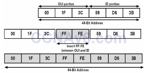
Figure 7.18 – Creating the EUI-64 Address
The second step of EUI-64 addressing entails the setting of the seventh bit of the 64-bit address. This seventh bit is used to identify whether the MAC address is unique. If this bit is set to 1, this indicates that the MAC address is a globally managed MAC address – which means that the MAC address has been assigned by a vendor. If this bit is set to 0, this indicates that the MAC address is locally assigned – which means that the MAC address has been added by the administrator, for example. To clarify this statement further, as an example, MAC address 02:1F:3C:59:D6:3B would be considered a globally-assigned MAC address, while MAC address 00:1F:3C:59:D6:3B would be considered a local address. This is illustrated in Figure 7.19 below:
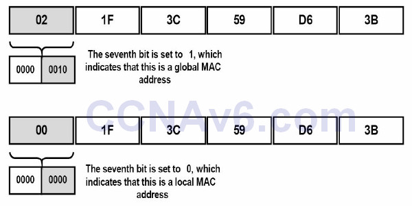
Figure 7.19 – Determining Local and Global MAC Addresses
The following configuration example illustrates how to assign an IPv6 prefix to an interface and configure the router to create the interface ID automatically using EUI-64 addressing:
R2(config)#interface FastEthernet0/0
R2(config-if)#ipv6 address 3fff:1a2b:3c4d:5e6f::/64 eui-64
R2(config-if)#exit
Following this configuration, the show ipv6 interface command can be used to validate the IPv6 interface ID assigned to the FastEthernet0/0 interface, as illustrated below:
R2#show ipv6 interface FastEthernet0/0
FastEthernet0/0 is up, line protocol is up
  IPv6 is enabled, link-local address is FE80::213:19FF:FE86:A20
  Global unicast address(es):
    3FFF:1A2B:3C4D:5E6F:213:19FF:FE86:A20, subnet is 3FFF:1A2B:3C4D:5E6F::/64 [EUI]
  Joined group address(es):
    FF02::1
    FF02::2
    FF02::1:FF86:A20
  MTU is 1500 bytes
...
[Truncated Output]
To validate the creation of the EUI-64 address, you can verify the complete IPv6 address by also viewing the MAC address for the specified interface using the show interface command:
R2#show interface FastEthernet0/0
FastEthernet0/0 is up, line protocol is up
  Hardware is AmdFE, address is 0013.1986.0a20 (bia 0013.1986.0a20)
    Internet address is 10.0.1.1/30
From the output above, you can see that the EUI-64 address is indeed valid and is based on the MAC address of the interface. In addition, the address is global, as the seventh bit has been enabled (i.e., contains a non-zero value).
Finally, the [link-local] keyword is used to assign a Link-Local address to the interface. By default, it is important to remember that an IPv6 prefix does not have to be enabled on the interface in order for a Link-Local address to be created dynamically. Instead, if the ipv6 enable interface configuration command is issued under an interface, a Link-Local address is created automatically for that interface using EUI-64 addressing.
To configure a Link-Local address manually, you must assign an address within the FE80::/10 Link-Local address block. The following configuration example illustrates how to configure a Link-Local address on an interface:
R3(config)#interface FastEthernet0/0
R3(config-if)# ipv6 address fe80:1234:abcd:1::3 link-local
R3(config-if)#exit
Following this configuration, the show ipv6 interface [name] command can be used to validate the manual configuration of the Link-Local address, as shown in the output below:
R3#show ipv6 interface FastEthernet0/0
FastEthernet0/0 is up, line protocol is up
  IPv6 is enabled, link-local address is FE80:1234:ABCD:1::3
  Global unicast address(es):
    2001::1, subnet is 2001::/64
  Joined group address(es):
   FF02::1
    FF02::2
    FF02::1:FF00:1
    FF02::1:FF00:1111
  MTU is 1500 bytes
...
[Truncated Output]
NOTE: When configuring Link-Local addresses manually, if Cisco IOS software detects another host using one of its IPv6 addresses, an error message will be printed on the console and the command will be rejected. Be very careful when configuring Link-Local addressing manually.
Subnetting with IPv6
As you have already learned, IPv6 addresses are allocated to companies with a prefix. The host part of the address is always 64 bits and the standard prefix is usually 48 bits or /48. This leaves 16 bits free for network administrators to use for subnetting.
Because the same rules apply to both IPv4 and IPv6, as far as network addressing is concerned, you can have only one network per network segment. You can’t break the address and use some host bits on one part of the network and some on another.
If you look at the addressing in the chart below, the situation should make more sense:

You need never concern yourself about running out of host bits per subnet because each subnet has over 18 quintillion hosts. It’s unlikley that any organisation would ever run out of subnets, but even if this were the case, another global routing prefix could easily be provided by the ISP.
Let’s say, for example, that you are allocated the global routing prefix 0:123:abc/48. This address is occupying three sections of a full IPv6 address and each section or quartet is 16 bits, so you have 48 bits used so far. The host portion will require 64 bits, leaving you 16 bits for allocation as subnets.
You would simply start counting up in hex from zero (zero is legal) and keep going. For your hosts you would do the same, unless you wanted to reserve the first few addresses for servers on the segment, for example.
Let me use a simpler prefix for our example – 2001:123:abc/48. The first subnet would be all zeros and, of course, the first host on each subnet would be all zeros, which is legal (since you don’t reserve the all 0s and all 1s addresses in IPv6). You would represent the all zeros host by using the abbreviated format of ::. Here are the first few subnets and host addresses:
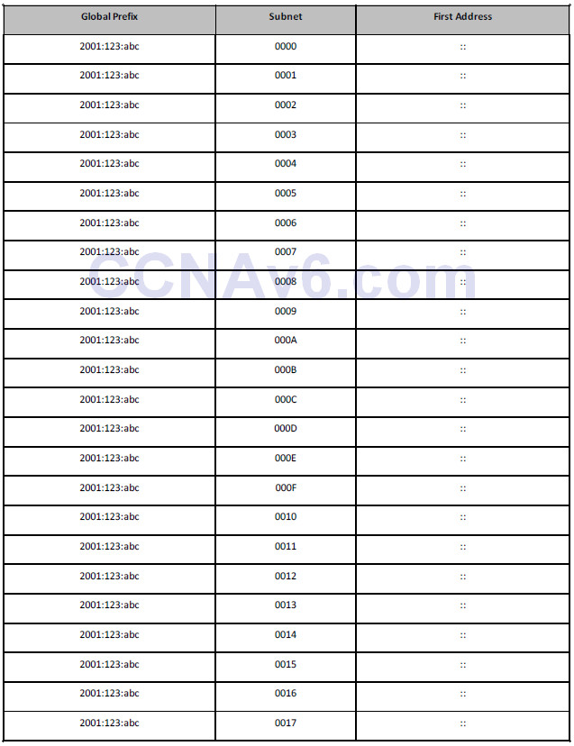
You have already noticed a difference from IPv4 addressing rules, I’m sure, in that you can use the all zeros subnet and the first subnet address is always all zeros. Looking at a simple network topology, you could allocate the subnets in the fashion below:
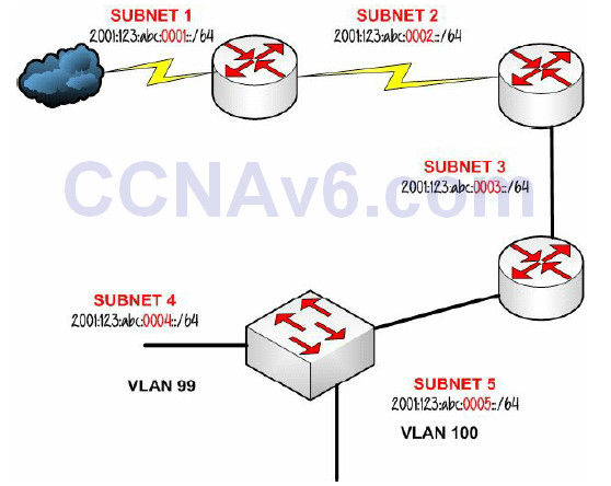
Figure 7.20 – Allocating IPv6 Subnets
Can it really be that easy? If you recall from the IPv4 subnetting section, it can become somewhat of a nightmare to figure that out, as well as having to work out how many hosts and subnets and remembering to exclude certain addresses. IPv6 subnetting is far easier. You may not be allocated a 48-bit prefix, it could be /56 for a home network or smaller, but the principle would be the same. You can also subnet off the bit boundary, but this would be most unusual and unfair of Cisco to expect you to go into that amount of detail in the short amount of time you have in the exam. Hopefully, the exam won’t be a mean attempt to catch you out, but you never know. Just in case, here is an example of a /56 prefix length address:
2001:123:abc:8bbc:1221:cc32:8bcc:4231/56
The prefix is 56 bits, which translates to 14 hex digits (14 x 4 = 56), so you know that the prefix will take you to the middle of a quartet. This is where you could make a mistake in the exam. You must zero hex bits 3 and 4 in the quartet before the prefix breaks:
2001:123:abc:8b00:0000:0000:0000:0000/56
I’ve underlined the quartet where the bit boundary is broken. In haste and due to time pressures in the exam, you could well miss this important step. Remember that you would also abbreviate this address (the first host on the first subnet) to:
2001:123:abc:8b00::/56
If they do try to catch you out in the exam, it would probably be an attempt to have you remove the trailing zeros from the quartet before the bit boundary is broken:
2001:123:abc:8b::/56
The above abbreviation is illegal.
You can steal bits from the host portion to use for subnets, but there should never be a reason to and it would break the ability to use many of the features IPv6 was invented to utilise, including stateless autoconfiguration.
IPv6 Compared to IPv4
A network engineer should have a very clear picture of the advantages IPv6 brings over IPv4. Looking at the enhancements of IPv6, we can summarise the following:
• Ipv6 has an expanded address space, from 32 bits to 128 bits.
• IPv6 uses hexadecimal notation instead of dotted-decimal notation (as in IPv4).
• IPv6 addresses are globally unique due to the extended address space, eliminating the
need for NAT.
• IPv6 has a fixed header length (40 bytes), allowing vendors to improve switching efficiency.
• IPv6 supports enhanced options (that offer new features) by placing extension headers
between the IPv6 header and the Transport Layer header.
• IPv6 offers address autoconfiguration, providing for dynamic assignment of IP addresses
even without a DHCP server.
• IPv6 offers support for labeling traffic flows.
• IPv6 has security capabilities built in, including authentication and privacy via IPSec.
• IPv6 offers MTU path discovery before sending packets to a destination, eliminating the
need for fragmentation.
• IPv6 supports site multi-homing.
• IPv6 uses the ND (Neighbor Discovery) protocol instead of ARP.
• IPv6 uses AAAA DNS records instead of A records (as in IPv4).
• IPv6 uses Site-Local addressing instead of RFC 1918 (as in IPv4).
• IPv4 and IPv6 use different routing protocols.
• IPv6 provides for Anycast addressing.
Section 7 Questions
1. IPv6 addresses must always be used with a subnet mask. True or false?
2. Name the three types of IPv6 addresses.
3. Which command enables IPv6 on your router?
4. The 0002 portion of an IPv6 address can be shortened to just 2. True or false?
5. How large is the IPv6 address space?
6. With IPv6, every host in the world can have a unique address. True or false?
7. IPv6 does not have natively integrated security features. True or false?
8. IPv6 implementations allow hosts to have multiple addresses assigned. True or false?
9. How can the broadcast functionality be simulated in an IPv6 environment?
10. How many times can the double colon (::) notation appear in an IPv6 address?
Section 7 Answers
1. False.
2. Unicast, Multicast, and Anycast.
3. The ipv6 unicast-routing command.
4. True.
5. 128 bits.
6. True.
7. False.
8. True.
9. By using Anycast.
10. One time.
Section 7 Lab
IPv6 Concepts Lab
Test the IPv6 concepts and commands detailed in this module on a pair of Cisco routers that are directly connected:
• Enable IPv6 Global Unicast routing on both routers
• Manually configure an IPv6 address on each of the connected interfaces. For example:
° 2001:100::1/64 on R1
° 2001:100::2/64 on R2
• Verify the configuration using the show ipv6 interface and show ipv6 interface prefix
commands
• Test direct ping connectivity
• Repeat the test using IPv6 stateless autoconfiguration (ipv6 address autoconfig default)
• Repeat the test using EUI-64 addresses (IPv6 address 2001::/64 EUI-64)
• Hard code an interface Link-Local address: IPv6 address fe80:1234:abcd:1::3 Link-Local
• Verify the IPv6 routing table
Visit www.in60days.com and watch me do this lab for free.
Hex Conversion and Subnetting Practice
Please spend the rest of this day’s lesson practicing these critical topics:
• Conversion from decimal to hex (random numbers)
• Conversion from hex to decimal (random numbers)
• IPv6 subnetting (random networks and scenarios)
