Section 5 Tasks
• Read today’s lesson notes (below)
• Review yesterday’s lesson notes
• Complete today’s lab
• Read the ICND1 cram guide
• Spend 15 minutes on the subnetting.org website
Welcome to what many people find to be one of the hardest areas of the CCNA syllabus to understand. In order to understand IP addressing for the CCNA exam, we must cover binary mathematics and the hexadecimal numbering system, classes of addresses, powers of two and rules such as subnet zero, and Broadcast and network addresses, as well as formulas to work out subnets and host addresses.
Don’t worry, though; this is a process, not a one-off event, so follow my notes and then feel assured that we will be coming back to review these concepts many times.
Today you will learn about the following:
• IP addressing (using binary and hexadecimal)
• Using IP addresses
• Subnetting
• Easy subnetting
• Network design
• Using VLSM
• Slicing down networks
This module maps to the following CCNA syllabus requirements:
• Describe the operation and necessity of using private and public IP addresses for IPv4 addressing
• Identify the appropriate IPv4 addressing scheme using VLSM and summarisation to satisfy addressing requirements in a LAN/WAN environment
• Troubleshoot and correct common problems associated with IP addressing and host configurations
Cisco have put some VLSM requirements into the ICND1 and the ICND2 exams. More emphasis on this seems to be in the ICND2 exam, but you need to prepare yourself for questions in both exams equally. VLSM will be covered, but you need to understand IP addressing and subnetting first.
IP Addressing
All devices on a network need some way to identify themselves as a specific host. Early networks simply used a naming format, and a server on the network kept a map of MAC addresses to host names. Tables quickly grew very large and with this grew issues such as consistency and accuracy (see Figure 5.1 below). IP addressing effectively resolved this issue.
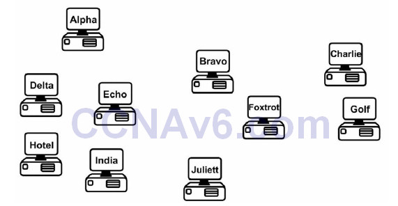
Figure 5.1 – Device Naming Tables Became Too Cumbersome
IP Version 4
IP version 4 (IPv4) was devised to resolve the device naming issue. IPv4 uses binary to apply an address to network devices. IPv4 addresses use 32 binary bits divided into four groups of eight (octets). The following is an example of an IPv4 address in binary:
11000000.10100011.11110000.10101011
which you would see in decimal as:
192.163.240.171
Each binary bit represents a decimal number, and you can use or not use the number by placing a 1 or a 0, respectively, in the relevant column. The eight columns are as follows:

In the chart above, you can see that only the first two decimal numbers are used (those with 1s beneath them), which produces the value 128 + 64 = 192.
Binary
In order to understand how IP addressing works, you need to understand binary mathematics (sorry). Computers and networking equipment do not understand decimal. We use decimal because it is a numbering system using 10 digits, invented by a caveman millenia ago when he realised he had 10 digits on his hands that could be used for counting dinosaurs as they walked past his cave.
Computers and networking equipment can only understand electrical signals. Since an electrical signal is either on or off, the only numbering system that will work is binary. Binary uses only two numbers, a 0 or a 1. A 0 means there is no electrical pulse on the wire and a 1 means that there is a pulse on the wire.
Any number can be made up using binary values. The more binary values you add, the larger the number becomes. For every binary value you add, you double the next number (e.g., 1 to 2 to 4 to 8 to 16, and so on into infinity), starting at the right and moving left. With two binary digits, you can count up to 3. Just place a 0 or a 1 in the column to decide whether you want to use that value.
Let’s start with only two binary values in columns 1 and 2:

If you use eight binary bit places (an octet), you can get any number from 0 up to 255. You can see that the numbers start from the right and move across to the left:

If you add a 0 to each of these columns, you have a value of 0 in decimal:
If you add a 1 to each of these columns, you have a value of 255 in decimal:

Don’t believe me?
128 + 64 + 32 + 16 + 8 + 4 + 2 + 1 = 255
So logic dictates that you can actually make any number from 0 to 255 by placing a 0 or a 1 in various columns, for example:

32 + 8 + 4 = 44
IP addressing and subnetting are based on the fundamentals above. Table 5.1 below summarises what you know so far. Pay special attention to this table because the values can be used for any subnet mask (more on that later).
Table 5.1 – Binary Values

Make up some of your own binary numbers to ensure that you understand this concept fully.
Hexadecimal
Hexadecimal (or hex) is an alternative numbering system. Rather than counting in 2s or by 10, 16 numbers or characters are used. Hex starts at 0 and goes all the way up to F, as illustrated below:
0 1 2 3 4 5 6 7 8 9 A B C D E F
Each hexadecimal digit actually represents four binary digits, as shown below in Table 5.2:
Table 5.2 – Decimal, Hex, and Binary Digits

Converting from binary to hex to decimal is fairly simple, as shown in Table 5.3 below:
Table 5.3 – Conversion of Binary to Hex to Decimal

Hex is a more manageable counting system for humans than binary, but it’s close enough to binary to be used by computers and networking equipment. Any number can be made using hex, as it can use binary or decimal; just count in multiples of 16 instead, for example:
1 x 16 = 16
16 x 16 = 256
256 x 16 = 4096
…and so on.

Counting in hex, therefore, goes 0 1 2 3 4 5 6 7 8 9 A B C D E F 10 11 12 13 14 15 16 17 18 19 1A 1B 1C 1D 1E 1F 20 21 22, etc., to infinity. 1A (above), for example, is an A in the 1 column and a 1 in the 16 column: A = 10 + 16 = 26.
When converting binary to hex, it makes the task easier if you break the octet into two groups of four bits. So 11110011 becomes 1111 0011. 1111 is 8 + 4 + 2 + 1 = 15, and 0011 is 2 + 1 = 3. 15 is F in hex and 3 is 3 in hex, giving us the answer F3. You can check Table 5.2 to confirm this.
Hex to binary is carried out using the same process. For example, 7C can be split into 7, which is 0111 in binary, and C (12 in decimal), which is 1100 in binary. The answer, then, is 01111100.
Converting Exercise
Here are some examples for you to try. Write out the charts above for working out hex and binary (i.e., for hex, a 1 column, then a 16 column, then a 256 column, and so on):
1. Convert 1111 to hex and decimal.
2. Convert 11010 to hex and decimal.
3. Convert 10000 to hex and decimal.
4. Convert 20 to binary and hex.
5. Convert 32 to binary and hex.
6. Convert 101 to binary and hex.
7. Convert A6 from hex to binary and decimal.
8. Convert 15 from hex to binary and decimal
9. Convert B5 from hex to binary and decimal.
It would be useful in the exam to write out Table 5.2 to help you work out any binary to hex to decimal conversions.
The rule for using IP addressing is that each address on the network must be unique to that host (i.e., it can’t be shared). Some addresses can’t be used for hosts. This will be covered in more detail later, but for now, know that you can’t use an address which is reserved for the entire network, a Broadcast address, or addresses reserved for testing. In addition, three groups are reserved for use on internal networks to save addresses.
Because of the rapid growth of network sizes, each IP address must be used in conjunction with a subnet mask. The subnet mask is there to tell the network devices how to use the numbers in the IP address. The reason for this is that some of the addresses available for hosts on your network can actually be used to chop down the network into smaller chunks or subnets.
An example of an IP address with a subnet mask is 192.168.1.1 255.255.255.240.
Address Classes
You need to know this and you don’t! I know, I’m not helping much, but address classes are actually only significant historically, so as a new Cisco engineer, you might become confused when you look at the old rules and try to apply them to new methods of network design.
We still refer to groups of IP addresses as classes, but with the introduction of subnet masking and VLSM, they are actually no longer applicable to network design. Address classes are useful to know, though, because they show us which parts of the IP address we can and can’t use for our mini-networks (subnets).
When IPv4 was first invented, addresses were divided into classes. The classes of addresses were then allocated to companies on an as-needed basis. The bigger the company, the bigger the address class. The address classes were assigned letters, A through E. A Class A address was reserved for the biggest networks. A Class A address can be numbered from 1 to 126 in the first octet. The reason for this is that the first bit on the first octet must be 0. If you have 0 in the first octet, then the remaining values can only go from 1 to 126, for example:
00000001 = 1
01111111= 126
You can’t have an address of all 0s on a network. If you actually add the other three octets, then you can see Class A addresses in full, for example:
10.1.1.1
120.2.3.4
126.200.133.1
These are all Class A addresses because they are within the range of 1 to 126. 127 is not a permitted number for IP addresses; 127.0.0.1 is actually an address used to test whether TCP/IP is working on your device.
A Class B address must have the first two bits of the first octet set to 10. This means that the first octet can only use the numbers 128 to 191, for example:
10000000 = 128
10111111 = 191
For Class C addresses, the first three bits on the first octet must be set to 110, giving us addresses 192 to 223, for example:
11000000 = 192
11011111 = 223
Class D addresses are used for multicasting (directed broadcasts), and Class E addresses are for experimental use only.
Subnet Mask Primer
I mentioned earlier that part of the address identifies the network and part of it identifies the host on the network. Subnet masks establish which parts are which. The difficulty is that it isn’t always easy to establish which is which by just looking at the subnet mask. This requires practise, and for the more difficult addresses, you must work them out by hand (or cheat by using a subnet calculator).
Even if you are not chopping your network into smaller parts, you must still apply a subnet mask to every address used. Each network class comes with a default subnet mask, for example:
Class A = 255.0.0.0
Class B = 255.255.0.0
Class C = 255.255.255.0
When the binary bits are turned on, the network knows that this number is to be used for the network, not for a host on the network, as illustrated below:

The address above means that 192.168.12 is the network and 2 is a host on that network. Furthermore, any address starting with 192.168.12 is on the same network. You can see from the number in the first octet and the default subnet mask that this is a Class C network.
Remember the rule I mentioned earlier: You can’t use the network numbers for hosts, so the numbers below cannot be used on devices:
10.0.0.0
192.168.2.0
174.12.0.0
The other rule is that you can’t use the Broadcast address on each network or subnet. A Broadcast address goes to all devices on the network, so, logically, it can’t be used for devices. A Broadcast address is one in which all the host bits are active, or turned on:
10.255.255.255
192.168.1.255
In the examples above, each binary bit is turned on for the host portion.
Using IP Addresses
Next up, the practicalities of using IP addresses – which ones can be used and which ones can’t be used?
You know that there has been a huge explosion in the use of computers over the past two decades. A PC used to be a very expensive item which few people could afford; therefore, they were reserved for use by well-funded companies only. Today, nearly every house contains one or more computers.
The problem, of course, is that IPv4 was devised when only a limited number of devices were being used and there was no anticipation of this situation changing. As addresses were being allocated, it was realised that at the current rate of growth, we would quickly run out of available addresses.
Private IP Addresses
One of several solutions was to reserve some classes of addresses for anybody to use, as long as that address wasn’t used over the Internet. This range of addresses is known as private IP addresses, and this solution was created by two RFCs, 1918 and 4193. As a refresher, RFC stands for Request for Comments and is a means for engineers to submit ideas for networking methods, protocols, and technology advancements.
The ranges of private addresses are as follows:
10.x.x.x – any address starting with a 10
172.16.x.x to 172.31.x.x – any address starting with 172.16 to 172.31, inclusive
192.168.x.x – any address starting with 192.168
Subnetting
Subnetting allows you to steal bits of an IP address which were traditionally used for hosts on the network. You can now carve smaller networks from your larger network space, and these smaller networks are referred to as subnetworks, or subnets for short.
If you apply the default subnet masks to the three usable address classes, you will see the portions of the address you can’t use for carving out subnets, as illustrated in the chart below:

For example, if you take a Class C network with the default subnet mask

and steal some of the available host bits on the last octet

you get two stolen bits on the last octet. This gives you the following subnets, each with 62 hosts:

With a bigger network, you could have used host numbers 1 to 254, so you have less available host numbers to use here but the trade-off is more networks. The chart below shows how the four subnets were determined:

Delving into binary math, you can see that using the first two bits of the host address lets you use the binary combinations 00, 01, 10, and 11, and writing these out in full, as you see in the subnets column, gives you the subnets 0, 64, 128, and 192. To clarify this further, the first two rows in grey are subnet numbers and the remaining six rows are for use by host numbers on each subnet.
If you feel your head spinning right about now, this is normal. It takes a while for all of this to finally click, I’m afraid.
Easy Subnetting
Come exam day, or when troubleshooting a subnetting issue on a live network, you will want to get to your answer quickly and accurately. For these reasons, I devised an easy way to subnet, which is the subject of my Subnetting Secrets Amazon Kindle book. You won’t need to read it though to be honest, as I cover what you need to know in this book.
A very useful resource I’ve created is www.subnetting.org, which gives you free challenge questions to solve around subnetting and network design.
Classless Inter-Domain Routing
Classless Inter-Domain Routing (CIDR) was created by the Internet Engineering Task Force as a method to allocate blocks of IP addresses and to route IP packets. The main feature of CIDR we will examine here is using slash address notation to represent subnet masks. This is important because it saves time, it is used in the real world, and, if that isn’t enough, you will be given exam questions involving CIDR addresses.
With CIDR, instead of using the full subnet mask, you write down the number of binary bits used. For 255.255.0.0, for example, there are two lots of eight binary bits used, so this would be represented with a /16. For 255.255.240.0, there are 8 + 8 + 4 bits used, giving you /20.
When you refer to subnet masks or network masks in the context of internetworking, you would say “slash sixteen” or “slash twenty” to work colleagues and they would know that you are referring to a CIDR mask.
The Subnetting Secrets Chart
I’m about to save you many weeks of subnetting frustration. My Subnetting Secrets cheat chart has been used by thousands of CCNA and CCNP students all over the world to pass exams and ace technical interviews for networking roles.
Seriously. Until I stumbled across the easy way while studying for my CCNA several years ago, students were forced to write out network addresses in binary or go through painful calculations in order to get to the correct answer.
In order to write out the Subnetting Secrets chart, you will need a pencil and paper. You need to be able to write it out from memory because in your exam you will be given a whiteboard to use for any working out. You can also use pen and paper in any technical interviews.
On the top right side of your paper, write the number 1, and then to the left of that double it to 2, then 4, then 8, and keep doubling up to number 128. This is one binary octet:
![]()
Under the 128 and going down, write out the number you would get if you put a tick in the first box (the 128 box). Then the next number below that will be what you would get if you ticked the next box (64), and the next (32), and the next (16), and so on until you had ticked all eight boxes:
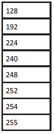
If you put together both parts, you will have the upper portion of the Subnetting Secrets cheat sheet:
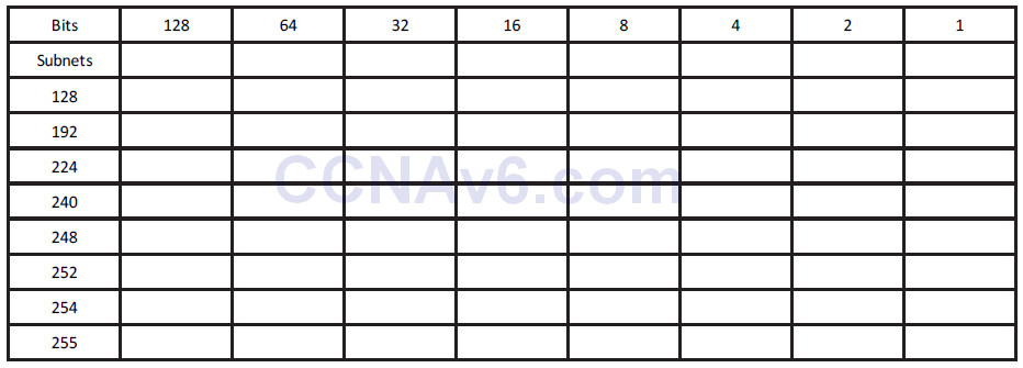
The top row represents your subnet increment and the left column your subnet mask. Using this part of the chart, you could answer any subnetting question in a few seconds. If you want to add the part of the chart which tells you how to answer any design question, such as “How many subnets and hosts will subnet mask ‘X’ give you,” just add a “powers of two” section.
One column will be “powers of two” and another will be “powers of two minus two.” The minus two is meant to cover the two addresses you can’t use, which are the subnet and the Broadcast addresses on the subnet. You start with the number 2 and double it as many times as you need to in order to answer the question.

You will probably learn best by jumping straight into an exam-style question:
Which subnet is host 192.168.1.100/26 in?
Well, you know that this is a Class C address and the default mask is 24 binary bits, or 255.255.255.0. You can see that instead of 24 there are 26 bits, so 2 bits have been stolen to make the subnet. Simply write down your Subnetting Secrets cheat sheet and tick two places (from the left) along the top row. This will reveal in what amount your subnets go up. You can then tick down two places in the subnets column to reveal the actual subnet mask.

Now you know two things: subnets will go up in increments of 64 (you can use 0 as the first subnet value) and your subnet mask for /26 ends in 192, so, in full, it is 255.255.255.192:
192.168.100.0 is your first subnet
192.168.100.64 is your second subnet
192.168.100.128 is your third subnet
192.168.100.192 is your last subnet
You can’t go any further than your actual subnet value, which is 192 in this example. But remember that the question is asking you to find host 100. You can easily see that the subnet ending in 64 is where host 100 would lie because the next subnet is 128, which is too high.
Just for completeness, I will add the host addresses and the Broadcast addresses. You can quickly work out the Broadcast address by taking the next subnet value and subtracting 1:

Consider the IP addresses to be values of anything from 0 to 255. Much like an odometer in a car, each number rolls up until it rolls back to 0 again, but the next box rolls over 1. Below are two sample octets. I jump up when we get to 0 2 to save space:

If you wanted to use the design part of the chart, you could. There is no need to for this question, but to see how it works, you just tick down two places in the subnets column because you stole 2 bits. From 8 bits in the last octet, that leaves you 6 bits for hosts, so tick down six places in the Hosts -2 column to reveal that you get 64 minus 2 bits per subnet, or 4 subnets, and 62 hosts per subnet:

Ready for another question? Of course you are.
Which subnet is host 200.100.2.210/25 in?
Same drill as before. You know this is a Class C address, and that to get from 24 to 25 bits, you need to steal 1 bit. Tick one across in the top row and then one down in the left column:

Therefore, your mask will be 255.255.255.128, and your subnets will go up in increments of 128. You can’t actually steal less than 1 bit for a Class C address; this will give you only two subnets:
200.100.2.0
and
200.100.2.128
You can already answer the question because you can see that host 210 will be in the second subnet. Just to demonstrate, I will write out the host and Broadcast addresses again:

Next question: Which subnet is 172.16.100.11/19 in?
You need to add 3 to 16 (the default Class B mask) to get to 19. Tick across three places in the top row of the chart to get the subnet increment, and then down three in the left column to get the subnet mask. You don’t need the lower portion of the chart for these types of questions.

Your subnet mask is 255.255.224.0, and you are subnetting on the third octet because the first two are reserved for the network address/default subnet mask.
Your subnets will be as follows:
172.16.0.0
172.16.32.0
172.16.64.0
172.16.96.0*
172.16.128.0
172.16.160.0
172.16.192.0
172.16.224.0
In the exam, please stop once you get to one subnet past the one your host is in, because going one past will make sure you have the right subnet. You are looking for host 100.11 on the 172.16 network; the asterisk in the list of subnets above denotes the subnet that the host number resides in.
If, for some reason, in the exam they asked you to identify the host addresses and Broadcast address (for extra points), you can easily add these. I will put them in for the first few subnets:

In the exam, they may well try to trick you by adding Broadcast addresses as options for host addresses, or even subnet addresses for host addresses. This is why you need to be able to identify which is which. You will also come across the same issue on live networks, where other engineers have tried to add the wrong address to an interface.
Next question: Which subnet is host 172.16.100.11/29 in?
As you can see by now, you can use any mask you wish with most any subnet. I could have asked you about the address 10.100.100.1/29, so don’t let the fact that you have a Class A address with subnet bits going into the second, third, or fourth octet put you off.
You need to steal 13 bits for the subnet mask but the subnetting chart has only eight places. Since you are looking at the easy way to subnet, just focus on the part of the chart which the remaining numbers spill over into. If you drew another chart next to the one you had just filled up, you would have five places filled up (8 + 5 = 13 bits):
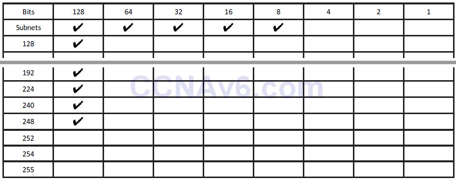
From the chart above, you can see that the subnet mask is 255.255.255.248. The 255 in the third octet is there because you filled it up whilst moving over into the fourth octet. The subnets are also going up in increments of 8.
You could start off with 172.16.0.0, but the problem with that is it would take quite some time to count up in multiples of 8 before you got to 172.16.100.11 this way, and the exam is a timed one. Therefore, you need to fast track the counting process.
If you start counting up in increments of 8, you would get the following:
172.16.0.0
172.16.0.8
172.16.0.16, and you could keep counting up to
172.16.1.0
172.16.1.8, and keep counting up to
172.16.20.0
172.16.20.8
This would take a very long time because there are over 8000 subnets (2 to the power of 13 gives you 8192, and you can check this using the design section of the Subnetting Secrets cheatsheet).
Let’s presume that each third octet is going up one digit at a time (which it is). Why not jump up to 172.16.100.x to start with?
172.16.100.0
172.16.100.8*
172.16.100.16
From the above, you can see which subnet host 11 is in, and if you were asked to work out the Broadcast address, it would look like the chart below:

That is enough subnetting for now. We will revisit this subject many times over. For some network design examples using the lower part of the chart, please check out
www.in60days.com.
Remember also that there are a few subnetting resources available for you to use:
www.subnetting.org – subnetting question generator
www.youtube.com/user/paulwbrowning – my YouTube channel with free videos
Route Summarisation
There are many millions of routes on the Internet. If these routes all had to be stored individually, the Internet would have come to a stop many years ago. Route summarisation, also known as supernetting, was proposed in RFC 1338, which you can read online by clicking on the RFC - www.faqs.org/rfcs/rfc1338.html.
If you want to read a very comprehensive guide to route summarisation, then please grab a hold of Jeff Doyle’s excelling Cisco book Routing TCP/IP Volume 1, which is now in its second edition.
ZIP Codes
ZIP codes are used by the United States Postal Service to improve routing of letters to addresses within the USA (see Figure 5.2). The first digit represents a group of US states, and the second and third digits represent a region inside that group. The idea is that letters and parcels can be quickly routed by machine or by hand into the correct state and then forwarded to that state. When it reaches the state, it can be routed to the correct region. From there, it can be routed to the correct city and so on, until it is sorted into the correct mailbag for the local postal delivery person.
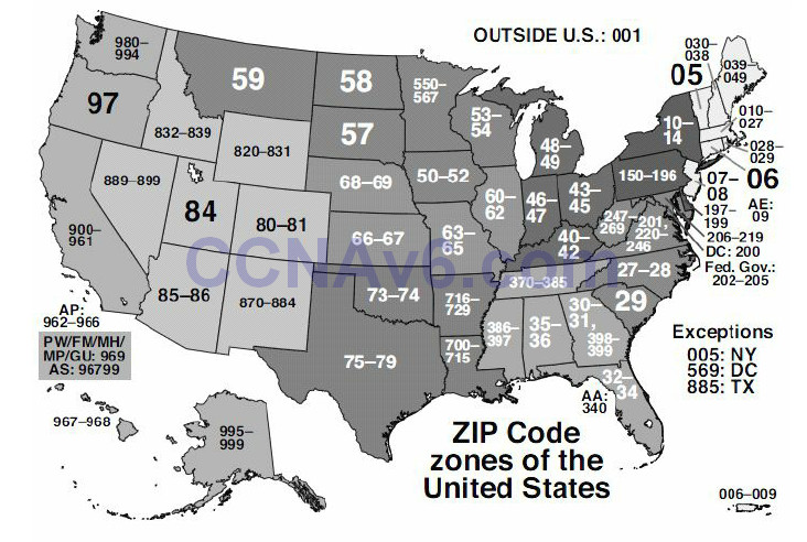
Figure 5.2 – US ZIP Codes
The ZIP code system was devised to make the routing of mail more accurate and efficient. For example, the sorting office in Atlanta doesn’t need to know which street in San Francisco the packet is destined for. Having to store that information would make the sorting process unworkable.
Route Summarisation Prerequisites
In order to use route summarisation on your network, you need to use a classless protocol (covered later), such as RIPv2, EIGRP, or OSPF. You also need to design your network in a hierarchical order, which will require careful planning and design. This means that you can’t randomly assign networks to various routers or LANs within your network.
Applying Route Summarisation
Let’s move on to an example of a network and what the problem will look like on your network if you don’t use route summarisation. In this example, this is how summarisation would work with a range of IP addresses on a network. The router in Figure 5.3 below has several networks attached. The first choice is to advertise all of these networks to the next-hop router. The alternative is to summarise these eight networks down to one route and send that summary to the next-hop router, which will cut down on bandwidth, CPU, and memory requirements.
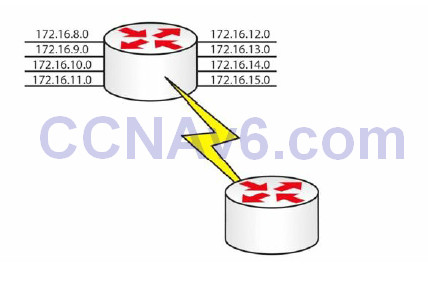
Figure 5.3 – An Example of Route Summarisation
The only way to work out a summary route is by converting the IP address into binary (sorry). If you don’t do this, then you will have no way of knowing whether you are advertising the correct summary route, which will lead to problems on your network.
Firstly, write out all of the network addresses in full and then the binary versions to the right of that, as illustrated below:
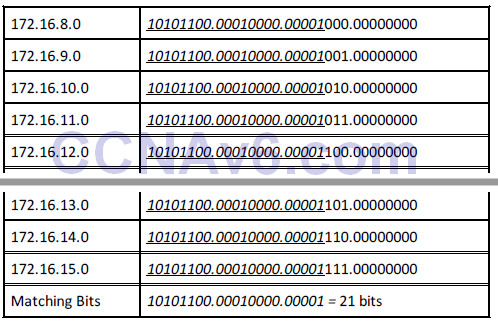
I have italicised and underlined the bits in each address that match. You can see that the first 21 bits match in every address, so your summarised route can reflect the following 21 bits:
172.16.8.0 255.255.248.0
One other significant advantage of using route summarisation is that if a local network on your router goes down, the summary network will still be advertised out. This means that the rest of the network will not need to update its routing tables or, worse still, have to deal with a flapping route (rapidly going up and down). I have chosen two exercises dealing with route summarisation for you to work out.
Exercise 1: Write out the binary equivalents for the addresses below, and then determine which bits match. I have written the first two octets for you to save time.
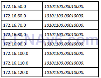
What summarised address would you advertise?
I would make it 172.16.50.0 255.255.128.0, or /17.
Exercise 2: The company below has three routers connected to their HQ router. They need to summarise the routes advertised from London 1, 2, and 3:
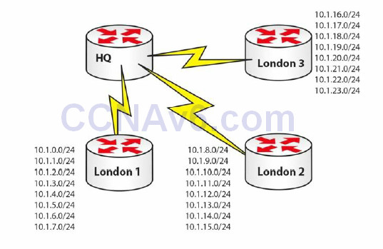
Figure 5.4 – Summarised Routes Advertised from London 1, 2, and 3
Let’s start with London 1:
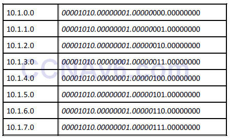
There are 21 common bits, so London 1 can advertise 10.1.0.0/21 to the HQ router.
And for London 2:
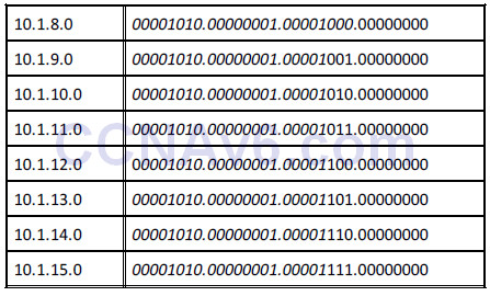
London 2 also has 21 common bits, so it can advertise 10.1.8.0/21 to the HQ router.
And on to London 3:
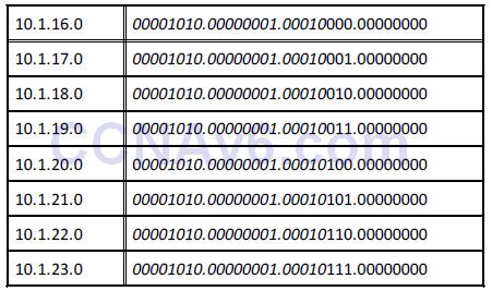
London 3 has 21 common bits also, so it can advertise 10.1.16.0/21 upstream to the HQ router.
You will be expected to understand route summarisation for the CCNA exam. If you can quickly work out the common bits, then you should be able to answer the questions quickly and accurately.
Here is the answer to Exercise 1:
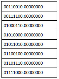
Variable Length Subnet Masking
Using VLSM
Look at the following network:
• 192.168.1.0/24 = 1 network with 254 hosts
While this may work fine, what if your network requires more than one subnet? What if your subnets have less than 254 hosts in them? Either situation requires some changes to be made. If you applied a /26 mask to your network instead, you would get this:
• 192.168.1.0/26 = 4 subnets with 62 hosts
If that wasn’t suitable, what about a /28 mask?
• 192.168.1.0/28 = 16 subnets with 14 hosts
You can refer back to the Subnetting Secrets cheat sheet design section to help you work out
how to apply VLSM to your network or to an exam question. With the /26 mask, you can see how many subnets and hosts you will get:
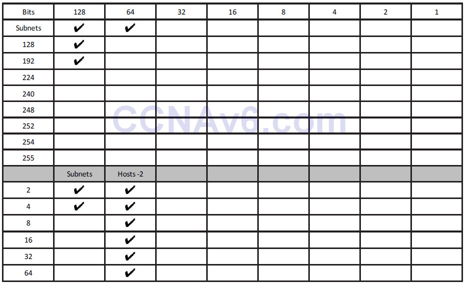
You have to take away 2 bits for the hosts, so you get four subnets, each with 62 hosts.
Slicing Down Networks
The point of VLSM is to take your network block and make it work for your particular network needs. Taking the typical network address of 192.168.1.0/24, with VLSM, you can use a /26 mask and now do this:
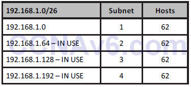
This may work fine until you realise that you have two smaller networks on your infrastructure which require 30 hosts each. What if three of your smaller subnets are taken (marked as IN USE above) and you have only one left (i.e., 192.168.1.0)? VLSM lets you take any of your chopped down subnets and chop them down even further. The only rule is that any IP address can be used only once, no matter which mask it has.
If you use the design section of the Subnetting Secrets cheat sheet, you will see which mask gives you 30 hosts:

The upper section of the chart (not shown here) tells us that three ticks down in the left column gives you a mask of 224 or /27 (3 stolen bits).
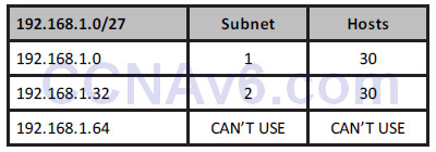
You can’t use the .64 subnet because this is already in use. You are now free to use either of the other two subnets. If you needed only one, you could chop down the remaining one to give you more subnets, each with fewer hosts.
Please also read bonus stuff on VLSM on the in60days.com website.
Troubleshooting IP Addressing Issues
Troubleshooting Subnet Mask and Gateway Issues
You may see a number of symptoms occurring whenever you have a problem with IP addressing, the subnet mask, or gateway issues. Some of the problems that might occur include the following:
• Network devices can communicate within their local subnet but are unable to communicate with devices outside the local network. This usually indicates that you have some type of issue with the gateway configuration or operation.
• Not having any type of IP communication, either internally or remote. This usually points to a major issue which might involve a lack of functionality on certain devices.
• Situations in which you can communicate with some IP addresses but not all of those that are available. This is usually the most difficult problem to troubleshoot because it has many possible causes.
One of the first things you should always do during the troubleshooting process for such
situations is double-check the IP address, the subnet mask, and the default gateway configuration on your devices. You should also check the documentation in order to verify this information. A great many issues stem from misconfigurations.
If you are installing network devices for the first time, very often you will manually type in the IP address information, along with the subnet mask and the default gateway. The recommendation is to verify this information before submitting it because human errors are rife in this area. Most enterprise networks have procedures for introducing new devices to the network, including testing the gateway and SNMP server reachablility.
If you need to gather information during the troubleshooting process, you might want to perform some packet capturing to see exactly which packets are sent between devices. If you see packets from hosts that are not on your network, you may have some kind of VLAN misconfiguration issue. If you suspect that your subnet mask is incorrect, you should check the parameters of other devices on your network. If the other machines work properly, you should use the same subnet mask on the device that is not working as expected and start testing again.
When using dynamic IP addressing (DHCP) to allocate IP address information to devices in your network, including the subnet mask and the default gateway, you should investigate the DHCP server configuration because that might be another area where problems may occur. Perhaps the DHCP server is misconfigured or the DHCP service is jammed, so you should include this step in your troubleshooting process. You must also remember to exclude reserved addresses from the DHCP pool because these addresses will usually be allocated to servers and router interfaces.
Other useful troubleshooting tools that will help you identify the point in the network where problems occur are traceroute and ping. We will cover these throughout the book and in labs.
Section 5 Questions
1. Convert 192.160.210.177 into binary (without using a calculator).
2. Convert 10010011 into decimal.
3. What is the private range of IP addresses?
4. Write out the subnet mask from CIDR /20.
5. Write out the subnet mask from CIDR /13.
6. 192.168.1.128/26 gives you how many available addresses?
7. What is the last host of the 172.16.96.0/19 network?
8. Starting with 192.168.1.0/24, with VLSM, you can use a /26 mask and generate which
subnets?
9. In order to use route summarisation on your network, you need to use what?
10. Write down the subnets 172.16.8.0 to 172.16.15.0, and work out the common bits and
what subnet mask you should use as a summary. Don’t look in the book before working
this out.
Section 5 Answers
1. 11000000.10100000.11010010.10110001.
2. 147.
3. 10.x.x.x – any address starting with a 10.
172.16.x.x to 172.31.x.x – any address starting with 172.16 to 172.31, inclusive.
192.168.x.x – any address starting with 192.168.
4. 255.255.240.0.
5. 255.248.0.0.
6. 62.
7. 172.16.127.254.
8. 192.168.1.0.0/26, 192.168.1.0.64/26, 192.168.1.0.128/26, and 192.168.1.0.192/26.
9. A classless protocol.
10. 172.16.8.0/21 (mask: 255.255.248.0).
Answers for the conversion exercises
1. Convert 1111 to hex and decimal
Hex = F
Decimal = 15
2. Convert 11010 to hex and decimal
Hex = 1A
Decimal = 26
3. Convert 10000 to hex and decimal
Hex = 10
Decimal = 16
4. Convert 20 to binary and hex
Binary = 10100
Hex = 14
5. Convert 32 to binary and hex
Binary = 100000
Hex = 20
6. Convert 101 to binary and hex
Binary = 1100101
Hex = 65
7. Convert A6 from hex to binary and decimal
Binary = 10100110
Decimal = 166
8. Convert 15 from hex to binary and decimal
Binary = 10101
Decimal = 21
9. Convert B5 from hex to binary and decimal
Binary = 10110101
Decimal = 181
Section 5 Lab
IP Addressing on Routers Lab
Topology

Purpose
Learn how to get used to configuring IP addresses on routers and pinging across a Serial
interface.
Walkthrough
1. Start off by establishing your Serial interface numbers, as they may differ from mine in the diagram above. Also, please establish which side has the DCE cable attached because this side will require the clock rate command.
Router>en
Router#sh ip interface brief
Interface       IP-Address  OK? Method Status               Protocol
FastEthernet0/0 unassigned  YES unset  administratively down down
FastEthernet0/1 unassigned  YES unset  administratively down down
Serial0/1/0     unassigned  YES unset  administratively down down
Vlan1           unassigned  YES unset  administratively down down
Router#
Router#show controllers Serial0/1/0
M1T-E3 pa: show controller:
PAS unit 0, subunit 0, f/w version 2-55, rev ID 0x2800001, version 2
idb = 0x6080D54C, ds = 0x6080F304, ssb=0x6080F4F4
Clock mux=0x30, ucmd_ctrl=0x0, port_status=0x1
line state: down
DCE cable, no clock rate
2. Add a hostname and IP address to one side. If this side is the DCE, add the clock rate.
Router#conf t
Enter configuration commands, one per line. End with CNTL/Z.
Router(config)#hostname RouterA
RouterA(config)#interface s0/1/0
RouterA(config-if)#ip add 192.168.1.1 255.255.255.0
RouterA(config-if)#clock rate 64000
RouterA(config-if)#no shut
%LINK-5-CHANGED: Interface Serial0/1/0, changed state to down
NOTE: If the ping doesn’t work, then double-check to make sure that you have added the clock rate command to the
correct router. Ensure that the cable is inserted correctly and use the show controllers serial x/x/x command,
inputting your own interface number.
RouterA(config-if)#
3. Add an IP address and hostname to the other router. Also, bring the interface up with the
no shut command.
Router>en
Router#conf t
Enter configuration commands, one per line. End with CNTL/Z.
Router(config)#hostname RouterB
RouterB(config)#int s0/1/0
RouterB(config-if)#ip address 192.168.1.2 255.255.255.0
RouterB(config-if)#no shut
%LINK-5-CHANGED: Interface Serial0/1/0, changed state to down
RouterB(config-if)#^Z
RouterB#
%LINK-5-CHANGED: Interface Serial0/1/0, changed state to up
4. Test the connection with a ping.
RouterB#ping 192.168.1.1
Type escape sequence to abort.
Sending 5, 100-byte ICMP Echos to 192.168.1.1, timeout is 2 seconds:
!!!!!
Success rate is 100 percent (5/5), round-trip min/avg/max = 31/31/32 ms
NOTE: If the ping doesn’t work, then double-check to make sure that you have added the clock rate command to the
correct router. Ensure that the cable is inserted correctly and use the show controllers serial x/x/x command,
inputting your own interface number.
Visit www.in60days.com and watch me do this lab for free.
Binary Conversion and Subnetting Practice
Please spend the rest of this day’s lesson practising these critical topics:
• Conversion from decimal to binary (random numbers)
• Conversion from binary to decimal (random numbers)
• Subnetting IPv4 (random networks and scenarios)
