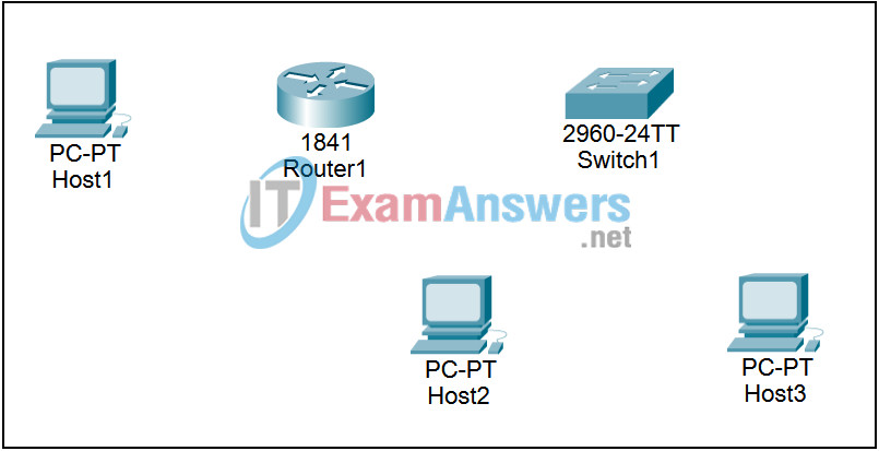
10.6.1 Packet Tracer – Creating a Small Lab Topology Answers
Topology

Addressing Table
This activity does not include an addessing table.
Learning Objectives
- Design the logical network
- Configure the physical lab topology
- Configure the logical LAN topology
- Verify LAN connectivity
Introduction:
In this lab, you have been given the network address 172.20.0.0/24 to subnet and provide the IP addressing for the networks shown in the Topology Diagrams. You must determine the number of networks needed then design an appropriate addressing scheme. Place the correct address and mask in the Addressing Table.
Task 1: Connect the logical network
Step 1. Using the following requirements correctly cable the topology:
- Router1’s Fa0/0 Connects to Host1’s FastEthernet port
- Router1’s Fa0/1 Connects to Switch1’s FastEthernet port
- Switch1’s Fa0/2 Connects to Host2’s FastEthernet port
- Switch1’s Fa0/3 Connects to Host3’s FastEthernet port
Task 2: Design the logical topology
Step 1. Given an IP address and mask of 172.20.0.0 / 24 (address / mask), design an IP addressing scheme that satisfies the following requirements:
| Subnet | Number of Hosts |
|---|---|
| SubnetA | 2 maximum |
| SubnetB | 6 maximum |
| SubnetC | 47 maximum |
| SubnetD | 125 maximum |
Step 2. Design SubnetD address block.
Begin the logical network design by satisfying the requirement of SubnetD, which requires the largest block of IP addresses. Refer to the subnet chart, and pick the first address block that will support SubnetD.
Step 3. Design SubnetC address block.
Begin the logical network design by satisfying the requirement of SubnetC. Refer to the subnet chart, and pick the first address block that will support SubnetC.
Step 4. Design SubnetB address block.
Begin the logical network design by satisfying the requirement of SubnetB. Refer to the subnet chart, and pick the first address block that will support SubnetB.
Step 5. Design SubnetA address block.
Begin the logical network design by satisfying the requirement of SubnetA, which requires the smallest block of IP addresses. Refer to the subnet chart, and pick the first address block that will support SubnetA.
Task 3: Configure the logical topology
Step 1. Document logical network settings.
Interface IP addresses:
- Host1 will use the first host address in SubnetA
- Host2 will use the first host address in SubnetB
- Host3 will use the second host address in SubnetB
- Router1’s Fa0/0 interface has been assigned the highest host address in SubnetA
- Router1’s Fa0/1 interface has been assigned the highest host address in SubnetB
NOTE: Use the IP Configuration button from the Desktop to configure PC’s
Task 4: Verify network connectivity
Use the Command Prompt button from the Desktop of each host to test connectivity to all other devices in the network.
