5.3.7 Packet Tracer – Router Packet Forwarding Answers
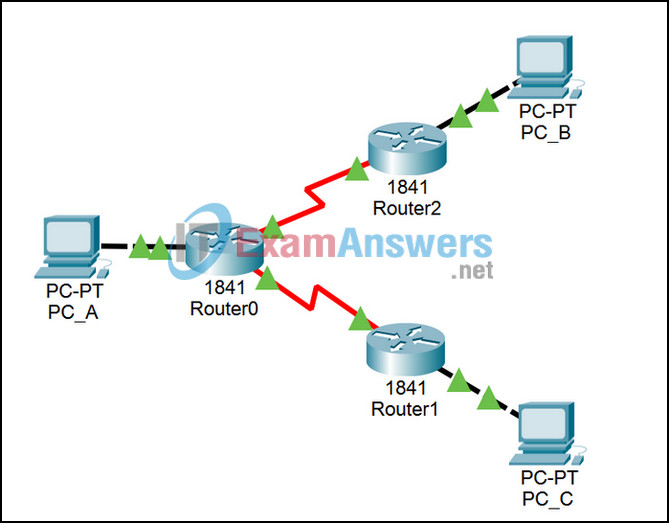
Topology

Learning Objectives
- Examine how routers forward packets when a route to the destination exists in the routing table
- Examine how routers forward packets when no specific route exists, but a default route has been configured
- Examine how routers forward packets when neither a specific route nor a default route exists
Introduction:
IP packets are forwarded between networks by routers that check their IP routing tables to find the next hop to the destination network. If there is an entry for the destination network in the routing table, the router will forward the packet out the interface indicated in the routing table. If there is no entry for the destination network in the routing table but there is a default route, the router will forward the packet out the interface indicated in the routing table for the default route. If there is no entry for the destination network in the routing table and there is no default route, the router will drop the packet.
This activity will use a configuration containing three routers, connecting three LANs. The first LAN is 10.1.1.0/24 that contains PC_A. The second LAN is 10.1.2.0/24 that contains PC_B. The last LAN 10.1.3.0/24 that contains PC_C. Router0 has a route to 10.1.2.0/24 and Router2 has a route to 10.1.1.0/24. So a ping from PC_A will reach PC_B and the reply will reach PC_A. Router0 has no route to 10.1.3.0/24 but has a default route out interface S0/0/1 (toward Router1). Router1 has no route to 10.1.1.0/24 and no default route. So a ping from PC_A will reach PC_C but the reply will be dropped by Router1.
Task 1: Run the Simulation using Scenario 0, from PC_A to PC_B
Step 1. Enter Simulation mode and send the packet.
The file loads with Scenario 0, which has a predefined packet from PC_A to PC_B, listed in the User Created PDU window at the lower right. Double click on the Fire button once in Realtime mode that will populate the ARP tables and make interpreting the routing behavior more clear. Click the Simulation tab to enter Simulation mode. The test packet will appear in both the Event List and on the logical topology. Use the Inspect Tool (the magnifying glass on the far right) to open up the routing tables for Router0, Router1, and Router2. The routing table windows may overlap each other, move them to compare all three tables at one time. Inspect the packet by clicking on the colored square in the Info column of the Event List.
Step 2. Trace the packet.
Use the Capture / Forward button to move the packet through the network. Inspect the packet at each step, particularly at the routers. Compare the OSI Model tab explanations of the packet’s processing with the displayed routing table. Note that both the ICMP echo request from PC_A to PC_B and the ICMP echo reply from PC_B back to PC_A can complete their journey because of the specific entries in the routing table.
Task 2: Run the simulation using Scenario 1, from PC_A to PC_C
Step 1. Move to Scenario 1.
Once you are done with Scenario 0, change to Scenario 1. You will still be in Simulation mode, so switch to Realtime mode long enough to allow the ping from PC_A to PC_C to show “Failed” in the Last Status column. This will populate the ARP tables and simplify the interpretation of the routing behavior. Switch back to Simulation mode. Inspect the packet by clicking on the colored square in the Info column of the Event List.
Step 2. Trace the packet.
Use the Capture / Forward button to move the packet through the network UNTIL it gets to PC_C. Click the Capture / Forward button to pause the packet. Inspect the packet at each step until PC_C, particularly at Router0 and Router1. Compare the OSI Model tab explanations of the packet’s processing with the displayed routing tables. Note that the ICMP echo request from PC_A to PC_C can complete its journey because a default static route exists on Router0 and the destination network is directly connected to Router1. However, these routes do not “point” in both directions.
Task 3: Continue running the simulation using Scenario 1, From PC_C to PC_A
Step 1. Trace the packet.
Use the Capture / Forward button to move the packet through the network. Inspect the packet at each step, in particular at Router1. Compare the OSI Model Tab explanations of the packet’s processing with the routing table of Router1, and note what happens to the ICMP echo reply packet from PC_C to PC_A.
