6.2.3.7 Packet Tracer – Troubleshooting a VLAN Implementation Scenario 1 (Instructor Version)
Instructor Note: Red font color or Gray highlights indicate text that appears in the instructor copy only.
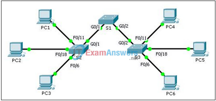
Topology

Addressing Table
| Device | Interface | IPv4 Address | Subnet Mask | Switch Port | VLAN |
|---|---|---|---|---|---|
| PC1 | NIC | 172.17.10.21 | 255.255.255.0 | S2 F0/11 | 10 |
| PC2 | NIC | 172.17.20.22 | 255.255.255.0 | S2 F0/18 | 20 |
| PC3 | NIC | 172.17.30.23 | 255.255.255.0 | S2 F0/6 | 30 |
| PC4 | NIC | 172.17.10.24 | 255.255.255.0 | S3 F0/11 | 10 |
| PC5 | NIC | 172.17.20.25 | 255.255.255.0 | S3 F0/18 | 20 |
| PC6 | NIC | 172.17.30.26 | 255.255.255.0 | S3 F0/6 | 30 |
Objectives
- Part 1: Test Connectivity between PCs on the Same VLAN
- Part 2: Investigate Connectivity Problems by Gathering Data
- Part 3: Implement the Solution and Test Connectivity
Scenario
In this activity, you will troubleshoot connectivity problems between PCs on the same VLAN. The activity is complete when PCs on the same VLAN can ping each other. Any solution you implement must conform to the Addressing Table.
Part 1: Test Connectivity between PCs on the Same VLAN
From the command prompt on each PC, ping between PCs on the same VLAN.
a. Can PC1 ping PC4?
No
b. Can PC2 ping PC5?
No
c. Can PC3 ping PC6?
No
Part 2: Investigate Connectivity Problems by Gathering Data
Step 1: Verify configuration on the PCs.
Based on your knowledge, verify if the following configurations for each PC is correct.
- IP address
- Subnet mask
Step 2: Verify the configuration on the switches.
Based on your knowledge, verify if the following configurations on the switches are correct.
- Ports assigned to the correct VLANs.
- Ports configured for the correct mode.
- Ports connected to the correct devices.
Step 3: Document the problem and the solutions.
List the problems and the solutions that will allow these PCs to ping each other. Keep in mind that there could be more than one problem or more than one solution.
PC1 to PC4
a. Explain the connectivity issues between PC1 and PC4.
PC1 is on VLAN 30 instead of VLAN 10. The G0/1 port on S1 is configured as an access port.
b. Record the necessary actions to correct the issues.
Issue the switchport access vlan 10 command on F0/11 interface on S2. Issue the switchport mode trunk command on G0/1 interfaces for S1 and S2.
PC2 to PC5
c. Explain the connectivity issues between PC2 and PC5.
PC5 is connected to the wrong port, and F0/18 is assigned to the wrong VLAN.
d. Record the necessary actions to correct the issues.
Move PC5 from F0/17 to F0/18 on S3 and assign F0/18 to VLAN 20. Issue the switchport mode trunk command on G0/1 interfaces for S1 and S2.
PC3 to PC6
e. What are the reasons why connectivity failed between the PCs?
IP address for PC6 is configured incorrectly. S1 G0/1 is configured in access mode. F0/6 on S3 is not assigned to a VLAN.
f. Record the necessary actions to correct the issues.
Configure IP address for PC6 to 172.17.30.26. Issue the switchport mode trunk command on G0/1 interface for S1 and S2. Assign F0/6 on S3 to VLAN 30.
Part 3: Implement the Solution and Test Connectivity
Verify PCs on the same VLAN can now ping each other. If not, continue to troubleshoot.
Suggested Scoring Rubric
Packet Tracer scores 70 points. Documentation in Part 2, Step 3 is worth 30 points.
