6.6.4 Packet Tracer – Trace and Time To Live Answers
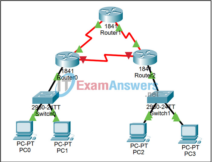
Topology

Learning Objectives
- Observe the operation of a trace
- Observe how a packet’s Time to Live is decremented in a routing loop
Introduction:
Several forms of the trace command are extremely useful as network troubleshooting tools. To issue the command from the Windows command line, the form to use is tracert (IP address, or URL if DNS is configured properly); to issue the command from IOS, the form to use is trace or traceroute (IP address, or URL if DNS is configured properly).
In this activity, you will examine trace, and see how it is built out of ping packets with different settings in the Time to Live field. In the second part of this activity, you will activate a routing loop by turning on a router interface, launching a packet into the loop, and observing how the Time to Live value is decremented until the packet is dropped.
Task 1: Examine the operation of a trace.
Step 1. Enter Simulation mode.
Click the Simulation tab to enter Simulation mode once the switch link lights are green (toggling between Realtime and Simulation mode will speed up this process). We want to capture only ICMP events. In the Event List Filters section, click the Edit Filters button. Select only ICMP events.
Step 2. Issue the trace.
From the command prompt of PC0, issue the command tracert 192.168.1.2 and press the Enter key. Minimize the command prompt window, the first packet should appear.
Step 3. Examine the first packet.
Examine the first packet that appears in the Event List by clicking on the colored Info square for that packet.
Step 4. Step through the simulation, examining the TTL for the outgoing packets and the replies.
Click the Capture / Forward button repeatedly until the entire tracert process is complete. Examine the packet via the PDU Information window at various points along its journey. Note that the tracert is built out of ping, more precisely, echo requests with increasing Time to Live settings. Restore the PC0 command window periodically to view the progress of the command output. When finished, click the Reset Simulation button.
Task 2: Observe how a packet’s Time to Live is decremented in a routing loop.
Step 1. Activate the routing loop.
Open Router0, and go to the Config tab. Find INTERFACE Serial0/0/1 (which has IP address 192.168.9.2), and change the Port Status to on. Because of previously configured static routes on each of the routers, a deliberate routing loop for packets to unknown destinations is activated when you turn on this interface. You can use the Inspect Tool (the magnifying glass at the right of the GUI) to look at the routing tables for each of the routers; note that the default static route for each router simply points to the next router.
Step 2. Add a complex PDU to an non-existent destination.
Use the Add Complex PDU button (the open envelope in the far right) to add a complex PDU from PC0. For the destination IP address, use 172.16.1.1, an address which does not exist anywhere on this network. For the sequence number, use 1, and for the time, use 0. Click on the Create PDU button. The default static routes configured on the routers will keep forwarding this packet until its Time to Live expires. Examine the first packet that appears in the Event List by clicking on the colored Info square for that packet.
Step 3. Step through the simulation.
Click the Capture / Forward button repeatedly and observe how this packet is forwarded around the routing loop. Examine the packet via the PDU Information window at various points along its journey, and note that the routers are decrementing the Time to Live. Continue until the packet is dropped and a notification is sent back to PC0. Imagine what the situation would be if IP packets did not have a Time to Live field.
