Section 31 Tasks
- Read today’s lesson notes (below)
- Complete today’s lab
- Read the ICND2 cram guide
- Spend 15 minutes on the subnetting.org website
The role of Spanning Tree Protocol (STP) is to prevent loops from occurring on your network by creating a loop-free logical topology, while allowing physical links in redundant switched network topologies. With the huge growth in the use of switches on networks, and the main goal of propagating VLAN information, the problem of frames looping endlessly around the network began to occur.
The previous CCNA exam required only a basic understanding of STP. The current version, however, expects you to have a very good grasp of the subject.
Today you will learn about the following:
- The need for STP
- STP Bridge ID
- STP Root Bridge election
- STP cost and priority
- STP Root and Designated Ports
- STP enhancements
- Troubleshooting STP
This lesson maps to the following CCNA syllabus requirement:
- Configure and verify PVSTP operation
- Describe root bridge election
- Spanning tree mode
The Need for STP
STP is defined in the IEEE 802.1D standard. In order to maintain a loop-free logical topology, every two seconds, switches pass Bridge Protocol Data Units (BPDUs). BPDUs are data messages used within a spanning tree topology to pass information about ports, addresses, priorities, and costs. The BPDUs are tagged with the VLAN ID.
Figure 31.1 below shows how loops can be created in a network. Because each switch learns about VLAN 20, it also advertises to other switches that it can reach VLAN 20. Soon enough, each switch thinks it is the source for VLAN 20 traffic and a loop is caused, so any frame destined for VLAN 20 is passed from switch to switch.
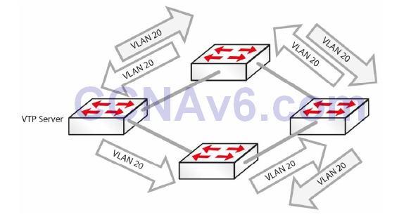
Figure 31.1 – How Loops Are Created.
STP runs an algorithm to decide which switch ports stay open, or active, as far as a particular VLAN is concerned, and which ones need to be shut for that particular VLAN.
All switches that reside in the Spanning Tree domain communicate and exchange messages using BPDUs. STP uses the exchange of BPDUs to determine the network topology, which is determined by the following three variables:
- The unique MAC address (switch identifier) that is associated with each switch
- The path cost to the Root Bridge associated with each switch port
- The port identifier (MAC address of the port) associated with each switch port
BPDUs are sent every two seconds, which allows for rapid network loop detection and topology information exchanges. The two types of BPDUs are Configuration BPDUs and Topology Change Notification BPDUs; only Configuration BPDUs will be covered here.
IEEE 802.1D Configuration BPDUs
Configuration BPDUs are sent by LAN switches and are used to communicate and compute the Spanning Tree topology. After the switch port initialises, the port is placed into the Blocking state and a BPDU is sent to each port in the switch. By default, all switches initially assume that they are the Root of the Spanning Tree, until they exchange Configuration BPDUs with other switches. As long as a port continues to see its Configuration BPDU as the most attractive, it will continue sending Configuration BPDUs. Switches determine the best Configuration BPDU based on the following four factors (in the order listed):
- Lowest Root Bridge ID
- Lowest Root path cost to Root Bridge
- Lowest sender Bridge ID
- Lowest sender Port ID
The completion of the Configuration BPDU exchange results in the following actions:
- A Root Switch is elected for the entire Spanning Tree domain
- A Root Port is elected on every Non-Root Switch in the Spanning Tree domain
- A Designated Switch is elected for every LAN segment
- A Designated Port is elected on the Designated Switch for every segment (all active ports on the Root Switch are also designated)
- Loops in the network are eliminated by blocking redundant paths
NOTE: These characteristics will be described in detail as you progress through this module.
Once the Spanning Tree network has converged, which happens when all switch ports are in a Forwarding or Blocking state, Configuration BPDUs are sent by the Root Bridge every Hello time interval, which defaults to two seconds. This is referred to as the origination of Configuration BPDUs. The Configuration BPDUs are forwarded to downstream neighbouring switches via the Designated Port on the Root Bridge.
When a Non-Root Bridge receives a Configuration BPDU on its Root Port, which is the port that provides the best path to the Root Bridge, it sends an updated version of the BPDU via its Designated Port(s). This is referred to as the propagation of BPDUs.
The Designated Port is a port on the Designated Switch that has the lowest path cost when forwarding packets from that LAN segment to the Root Bridge.
Once the Spanning Tree network has converged, a Configuration BPDU is always transmitted away from the Root Bridge to the rest of the switches within the STP domain. The simplest way to remember the flow of Configuration BPDUs after the Spanning Tree network has converged is to memorise the following four rules:
- A Configuration BPDU originates on the Root Bridge and is sent via the Designated Port.
- A Configuration BPDU is received by a Non-Root Bridge on a Root Port.
- A Configuration BPDU is transmitted by a Non-Root Bridge on a Designated Port.
- There is only one Designated Port (on a Designated Switch) on any single LAN segment.
Figure 31.2 below illustrates the flow of the Configuration BPDU in the STP domain, demonstrating the four simple rules listed above:
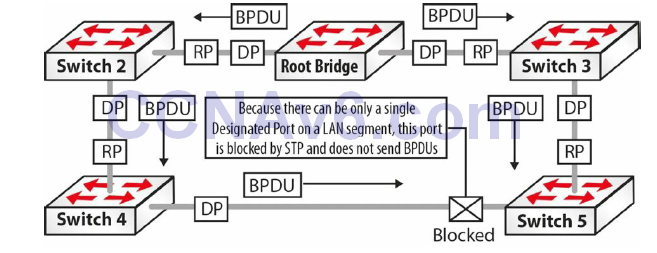
Figure 31.2 – A Configuration BPDU Flows throughout the STP Domain
- Referencing Figure 31.2, the Configuration BPDU is originated by the Root Bridge and sent out via the Designated Ports on the Root Bridge towards the Non-Root Bridge switches, Switch 2 and Switch 3.
- Non-Root Bridge Switch 2 and Switch 3 receive the Configuration BPDU on their Root Ports, which provide the best path to the Root Bridge.
- Switch 2 and Switch 3 modify (update) the received Configuration BPDU and forward it out of their Designated Ports. Switch 2 is the Designated Switch on the LAN segment for itself and Switch 4, while Switch 3 is the Designated Switch on the LAN segment for itself and Switch 5. The Designated Port resides on the Designated Switch and is the port that has the lowest path cost when forwarding packets from that LAN segment to the Root Bridge.
- On the LAN Segment between Switch 4 and Switch 5, Switch 4 is elected Designated Switch and the Designated Port resides on that switch. Because there can be only a single Designated Switch on a segment, the port on Switch 5 for that LAN segment is blocked. This port will not forward any BPDUs.
Spanning Tree Port States
The Spanning Tree Algorithm (STA) defines a number of states that a port under STP control will progress through before being in an active Forwarding state. 802.1D port states are as follows:
- Blocking – BPDUs received only (20 seconds)
- Listening – BPDUs sent and received (15 seconds)
- Learning – Bridging table is built (15 seconds)
- Forwarding – Sending/receiving data
- Disabled – Administratively down
A port moves through these states in the following manner:
- From initialisation to Blocking
- From Blocking to either Listening or Disabled
- From Listening to either Learning or Disabled
- From Learning to either Forwarding or Disabled
- From Forwarding to Disabled
STP timers are used in the process to control convergence:
- Hello – 2 seconds (time between each Configuration BPDU)
- Forward Delay – 15 seconds (controls durations of Listening/Learning states)
- Max Age – 20 seconds (controls the duration of the Blocking state)
Default convergence time is 30 to 50 seconds.
Spanning Tree Blocking State
A switch port that is in the Blocking state performs the following actions:
- Discards frames received on the port from the attached segment
- Discards frames switched from another port
- Does not incorporate station location into its address database
- Receives BPDUs and directs them to the system module
- Does not transmit BPDUs received from the system module
- Receives and responds to network management messages
Spanning Tree Listening State
The Listening state is the first transitional state that the port enters following the Blocking state. The port enters this state when STP determines that the port should participate in frame forwarding. A switch port that is in the Listening state performs the following actions:
- Discards frames received on the port from the attached segment
- Discards frames switched from another port
- Does not incorporate station location into its address database
- Receives BPDUs and directs them to the system module
- Receives, processes, and transmits BPDUs received from the system module
- Receives and responds to network management messages
Spanning Tree Learning State
The Learning state is the second transitional state the port enters. This state comes after the Listening state and before the port enters the Forwarding state. In this state, the port learns and installs MAC addresses into its forwarding table. A switch port that is in the Learning state performs the following actions:
- Discards frames received from the attached segment
- Discards frames switched from another port
- Incorporates (installs) station location into its address database
- Receives BPDUs and directs them to the system module
- Receives, processes, and transmits BPDUs received from the system module
- Receives and responds to network management messages
Spanning Tree Forwarding State
The Forwarding state is the final transitional state the port enters after the Learning state. A port in the Forwarding state forwards frames. A switch port that is in the Forwarding state performs the following actions:
- Forwards frames received from the attached segment
- Forwards frames switched from another port
- Incorporates (installs) station location information into its address database
- Receives BPDUs and directs them to the system module
- Processes BPDUs received from the system module
- Receives and responds to network management messages
Spanning Tree Disabled State
The Disabled state is not part of the normal STP progression for a port. Instead, a port that is administratively shut down by the network administrator, or by the system because of a fault condition, is considered to be in the Disabled state. A disabled port performs the following actions:
- Discards frames received from the attached segment
- Discards frames switched from another port
- Does not incorporate station location into its address database
- Receives BPDUs but does not direct them to the system module
- Does not receive BPDUs from the system module
- Receives and responds to network management messages
Spanning Tree Bridge ID
Switches in a Spanning Tree domain have a Bridge ID (BID), which is used to identify uniquely the switch within the STP domain. The BID is also used to assist in the election of an STP Root Bridge, which will be described later. The BID is an 8-byte field that is composed from a 6-byte MAC address and a 2-byte Bridge Priority. The BID is illustrated in Figure 31.3 below:

Figure 31.3 – Bridge ID Format
The Bridge Priority is the priority of the switch in relation to all other switches. The Bridge Priority values range from 0 to 65535. The default value for Cisco Catalyst switches is 32768.
Switch2#show spanning-tree vlan 2

VLAN0002
  Spanning tree enabled protocol ieee
  Root ID   Priority   32768
            Address    0009.7c87.9081
            Cost       19
            Port       1 (FastEthernet0/1)
            Hello Time 2 sec Max Age 20 sec Forward Delay 15 sec
  Bridge ID Priority   32770 (priority 32768 sys-id-ext 2)
            Address    0008.21a9.4f80
            Hello Time 2 sec Max Age 20 sec Forward Delay 15 sec
            Aging Time 300

Interface   Port ID             Designated                  Port ID
Name        Prio.Nbr  Cost  Sts Cost         Bridge ID      Prio.Nbr
----------  --------  ----  --- ------------ -------------- --------
Fa0/1       128.1     19    FWD 0 32768      0009.7c87.9081 128.13
Fa0/2       128.2     19    FWD 19 32770     0008.21a9.4f80 128.2
The MAC address in the output above is the hardware address derived from the switch backplane or supervisor engine. In the 802.1D standard, each VLAN requires a unique BID. Most Cisco Catalyst switches have a pool of 1024 MAC addresses that can be used as BIDs for VLANs. These MAC addresses are allocated sequentially, with the first MAC address in the range assigned to VLAN 1, the second to VLAN 2, the third to VLAN 3, and so forth. This provides the capability to support the standard range of VLANs, but more MAC addresses would be needed to support the extended range of VLANs. This issue was resolved in the 802.1t (Technical and Editoral corrections for 802.1D) standard.
Spanning Tree Root Bridge Election
By default, following initialisation, all switches initially assume that they are the Root of the Spanning Tree, until they exchange BPDUs with other switches. When switches exchange BPDUs, an election is held and the switch with the lowest Bridge ID in the network is elected the STP Root Bridge. If two or more switches have the same priority, the switch with the lowest order MAC address is chosen. This concept is illustrated in Figure 31.4 below:
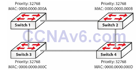
Figure 31.4 – Electing the STP Root Bridge
In Figure 31.4, four switches – Switch 1, Switch 2, Switch 3, and Switch 4 – are all part of the same STP domain. By default, all of the switches have a Bridge Priority of 32768. In order to determine which switch will become the Root Bridge, and thus break the tie, STP will select the switch based on the lowest-order MAC address. Based on this criterion, and referencing the information shown in Figure 31.4, Switch 1 will be elected the Root Bridge.
Once elected, the Root Bridge becomes the logical centre of the Spanning Tree network. This is not to say that the Root Bridge is physically at the centre of the network. Ensure that you do not make that false assumption.
NOTE: It is important to remember that during STP Root Bridge election, no traffic is forwarded over any switch in the same STP domain.
Cisco IOS software allows administrators to influence the election of the Root Bridge. In addition, administrators can also configure a backup Root Bridge. The backup Root Bridge is a switch that administrators would prefer to become the Root Bridge in the event that the current Root Bridge failed or was removed from the network.
It is always good practice to configure a backup Root Bridge for the Spanning Tree domain. This allows the network to be deterministic in the event that the Root Bridge fails. The most common practice is to configure the highest priority (i.e., the lowest numerical value) on the Root Bridge and then the second-highest priority on the switch that should assume Root Bridge functionality in the event that the current Root Bridge fails. This is illustrated in Figure 31.5 below:
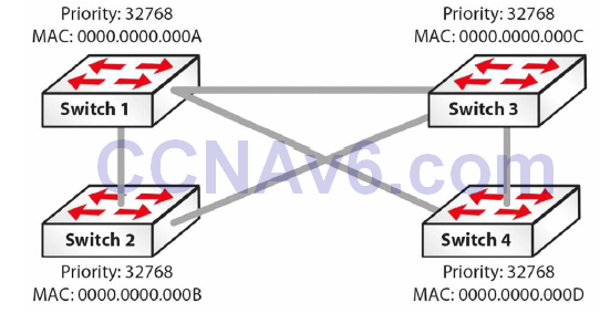
Figure 31.5 – Electing the STP Root Bridge (Continued)
Based on the configuration in Figure 31.5, the most likely switch to be elected as the Root Bridge in this network is Switch 1. This is because, although all priority values are the same, this switch has the lowest-order MAC address. In the event that Switch 1 failed, STP would elect Switch 2 as the Root Bridge, because it has the second-lowest MAC address. However, this would result in a suboptimal network topology.
To address this, administrators can manually configure the priority on Switch 1 to the lowest possible value (0) and that of Switch 2 to the second-lowest possible value (4096). This will ensure that in the event that the Root Bridge (Switch 1) fails, Switch 2 will be elected the Root Bridge. Because administrators are aware of the topology and know which switch would assume Root Bridge functionality, they created a deterministic network that is easier to troubleshoot. The Root ID is carried in BPDUs and includes the Bridge Priority and MAC address of the Root Bridge.
EXAM TIP: If you want to force a switch to become the Root Bridge, you can perform the following (see also Figure 31.6 below):
- You can manually set the priority
Switch(config)#spanning-tree vlan 2 priority ?
  <0-61440> bridge priority in increments of 4096
- Or set it as the Root Bridge using macro the commands primary or secondary
Switch(config)#spanning-tree vlan 2 root ?
  primary    Configure this switch as primary root for this spanning tree
  secondary  Configure switch as secondary root
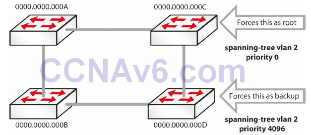
Figure 31.6 – Forcing a Switch to Become the Root Bridge
SwitchC#show spanning-tree vlan 5
VLAN0005
Spanning tree enabled protocol ieee
Root ID   Priority  0
Address  0000.0000.000c
This bridge is the root
Bridge ID   Priority  0 (priority 0 sys-id-ext 5)
SwitchD#show spanning-tree vlan 5
VLAN0005
Spanning tree enabled protocol ieee
Root ID   Priority  4096
Address  0000.0000.000d
Bridge ID   Priority  4096 (priority 8192 sys-id-ext 5)
SwitchD#show spanning-tree vlan 5
VLAN0005
Spanning tree enabled protocol ieee
Root ID   Priority  4096
Address  0000.0000.000d
Bridge ID   Priority  4096 (priority 8192 sys-id-ext 5)
Note that the VLAN number i s often added to the priori ty number, as shown in the output below:
SwitchA#show spanning-tree vlan 5
Bridge ID   Priority 32773 (priority 32768 sys-id-ext 5)
Address 0013.c3e8.2500
Hello Time  2 sec Max Age 20 sec Forward Delay 15 sec
Aging Time 300
Interface  Role  Sts   Cost   Prio.Nbr  Type
---------  ----  ---   ----   --------  ----
Fa0/15   Desg   FWD  19   128.15   P2p
Fa0/18   Desg   FWD   19   128.18  P2
Spanning Tree Cost and Priority
STP uses cost and priority values to determine the best path to the Root Bridge. These values are then used in the election of the Root Port, which will be described in the following section. It is important to understand the calculation of the cost and priority values in order to understand how Spanning Tree selects one port over another, for example.
One of the key functions of the STA is to attempt to provide the shortest path to each switch in the network from the Root Bridge. Once selected, this path is then used to forward data, whilst redundant links are placed into a Blocking state. STA uses two values to determine which port will be placed into a Forwarding state (i.e., is the best path to the Root Bridge) and which port(s) will be placed into a Blocking state. These values are the port cost and the port priority. Both are described in the sections that follow.
Spanning Tree Port Cost
The 802.1D specification assigns 16-bit (short) default port cost values to each port that is based on the port’s bandwidth. Because administrators also have the capability to assign port cost values manually (between 1 and 65535), the 16-bit values are used only for ports that have not been specifically configured for port cost. Table 31.1 below lists the default values for each type of port when using the short method to calculate the port cost:
Table 31.1 – Default STP Port Cost Values
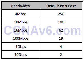
In Cisco IOS Catalyst switches, default port cost values can be verified by issuing the show spanning-tree interface [name] command, as illustrated in the following output, which shows the default short port cost for a FastEthernet interface:
VTP-Server#show spanning-tree interface FastEthernet0/2
Vlan             Role   Sts   Cost           Prio.Nbr Type
--------         ----   ---   ----      -------------
VLAN0050         Desg   FWD   19               128.2    P2p
The following output shows the same for long port cost assignment:
VTP-Server#show spanning-tree interface FastEthernet0/2
Vlan             Role Sts Cost           Prio.Nbr Type
--------         ---- --- ------    -------- ----
VLAN0050         Desg FWD 200000       128.2    P2p
It is important to remember that ports with lower (numerical) costs are more preferred; the lower the port cost, the higher the probability of that particular port being elected the Root Port. The port cost value is globally significant and affects the entire Spanning Tree network. This value is configured on all Non-Root Switches in the Spanning Tree domain.
Spanning Tree Root and Designated Ports
STP elects two types of ports that are used to forward BPDUs: the Root Port, which points towards the Root Bridge, and the Designated Port, which points away from the Root Bridge. It is important to understand the functionality of these two port types and how they are elected by STP.
Spanning Tree Root Port Election
STA defines three types of ports: the Root Port, the Designated Port, and the Non-Designated Port. These port types are elected by the STA and placed into the appropriate state (e.g., Forwarding or Blocking). During the Spanning Tree election process, in the event of a tie, the following values will be used (in the order listed) as tiebreakers:
- Lowest Root Bridge ID
- Lowest Root path cost to Root Bridge
- Lowest sender Bridge ID
- Lowest sender Port ID
NOTE: It is important to remember these tiebreaking criteria in order to understand how Spanning Tree elects and
designates different port types in any given situation. Not only is this something that you will most likely be tested on, but also it is very important to have a solid understanding of this in order to design, implement, and support internetworks in the real world.
The Spanning Tree Root Port is the port that provides the best path, or lowest cost, when the device forwards packets to the Root Bridge. In other words, the Root Port is the port that receives the best BPDU for the switch, which indicates that it is the shortest path to the Root Bridge in terms of path cost. The Root Port is elected based on the Root Bridge path cost.
The Root Bridge path cost is calculated based on the cumulative cost (path cost) of all the links leading up to the Root Bridge. The path cost is the value that each port contributes to the Root Bridge path cost. Because this concept is often quite confusing, it is illustrated in Figure 31.7 below:
NOTE: All but one of the links illustrated in Figure 31.7 are GigabitEthernet links. It should be assumed that the traditional 802.1D method is used for port cost calculation. Therefore, the default port cost of GigabitEthernet is 4, whilst that of FastEthernet is 19.
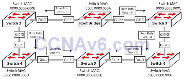
Figure 31.7 – Spanning Tree Root Port Election
NOTE: The following explanation illustrates the flow of BPDUs between the switches in the network. Along with other information, these BPDUs contain the Root Bridge path cost information, which is incremented by the ingress port on the receiving switch.
- The Root Bridge sends out a BPDU with a Root Bridge path cost value of 0 because its ports reside directly on the Root Bridge. This BPDU is sent to Switch 2 and Switch 3.
- When Switch 2 and Switch 3 receive the BPDU from the Root Bridge, they add their own path cost based on the ingress interface. Because Switch 2 and Switch 3 are both connected to the Root Bridge via GigabitEthernet connections, they add the path cost value received from the Root Bridge (0) to their GigabitEthernet path cost values (4). The Root Bridge path cost from Switch 2 and Switch 3 via GigabitEthernet0/1 to the Root Bridge is 0 + 4 = 4.
- Switch 2 and Switch 3 send out new BPDUs to their respective neighbours, which are Switch 4 and Switch 6, respectively. These BPDUs contain the new cumulative value (4) as the Root Bridge path cost.
- When Switch 4 and Switch 6 receive the BPDUs from Switch 2 and Switch 3, they increment the received Root Bridge path cost value based on the ingress interface. Since GigabitEthernet connections are being used, the value received from Switch 2 and Switch 3 is incremented by 4. The Root Bridge path cost to the Root Bridge on Switch 4 and Switch 6 via their respective GigabitEthernet0/1 interfaces is therefore 0 + 4 + 4 = 8.
- Switch 5 receives two BPDUs: one from Switch 4 and the other from Switch 6. The BPDU received from Switch 4 has a Root Bridge path cost of 0 + 4 + 4 + 4 = 12. The BPDU received from Switch 6 has a Root Bridge path cost of 0 + 4 + 4 + 19 = 27. Because the Root Bridge path cost value contained in the BPDU received from Switch 4 is better than that received from Switch 6, Switch 5 elects GigabitEthernet0/1 as the Root Port.
NOTE: Switches 2, 3, 4, and 6 will all elect their GigabitEthernet0/1 ports as Root Ports.
Further Explanation
To explain further and to help you understand the election of the Root Port, let’s assume that all ports in the diagram in Figure 31.7 above are GigabitEthernet ports. This would mean that in Step 5 above, Switch 5 would receive two BPDUs with the same Root Bridge ID, both with a Root path cost value of 0 + 4 + 4 + 4 = 12. In order for the Root Port to be elected, STP will progress to the next option in the tiebreaker criteria listed below (the first two options, which have already been used, have been removed):
- Lowest sender Bridge ID
- Lowest sender Port ID
Based on the third selection criteria, Switch 5 will prefer the BPDU received from Switch 4 because its BID (0000.0000.000D) is lower than that of Switch 6 (0000.0000.000F). Switch 5 elects port GigabitEthernet0/1 as the Root Port.
Spanning Tree Designated Port Election
Unlike the Root Port, the Designated Port is a port that points away from the STP Root. This port is the one in which the designated device is attached to the LAN. It is also the port that has the lowest path cost when forwarding packets from that LAN to the Root Bridge.
NOTE: Some people refer to the Designated Port as the Designated Switch. The terms are interchangeable and refer to the same thing; that is, this is the switch, or port, that is used to forward frames from a particular LAN segment to the Root Bridge.
The primary purpose of the Designated Port is to prevent loops. When more than one switch is connected to the same LAN segment, all switches will attempt to forward a frame received on that segment. This default behaviour can result in multiple copies of the same frame being forwarded by multiple switches – resulting in a network loop. To avoid this default behaviour, a Designated Port is elected on all LAN segments. By default, all ports on the Root Bridge are Designated Ports. This is because the Root Bridge path cost will always be 0. The STA election of the Designated Port is illustrated in Figure 31.8 below:
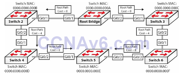
Figure 31.8 – Spanning Tree Designated Port Election
- On the segment between the Root Bridge and Switch 2, the Root Bridge GigabitEthernet0/1 is elected as the Designated Port because it has the lower Root Bridge path cost, which is 0.
- On the segment between the Root Bridge and Switch 3, the Root Bridge GigabitEthernet0/2 is elected as the Designated Port because it has the lower Root Bridge path cost, which is 0.
- On the segment between Switch 2 and Switch 4, the GigabitEthernet0/2 port on Switch 2 is elected as the Designated Port because Switch 2 has the lowest Root Bridge path cost, which is 4.
- On the segment between Switch 3 and Switch 6, the GigabitEthernet0/2 port on Switch 3 is elected as the Designated Port because Switch 3 has the lowest Root Bridge path cost, which is 4.
- On the segment between Switch 4 and Switch 5, the GigabitEthernet0/2 port on Switch 4 is elected as the Designated Port because Switch 4 has the lowest Root Bridge path cost, which is 8.
- On the segment between Switch 5 and Switch 6, the GigabitEthernet0/2 port on Switch 6 is elected as the Designated Port because Switch 6 has the lowest Root Bridge path cost, which is 8.
The Non-Designated Port is not really a Spanning Tree Port type. Instead, it is a term that simply means a port that is not the Designated Port on a LAN segment. This port will always be placed into a Blocking state by STP. Based on the calculation of Root and Designated Ports, the resultant Spanning Tree topology for the switched network that was used in the Root Port and Designated Port election examples is shown in Figure 31.9 below:
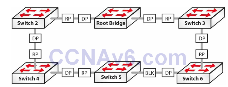
FIG 31.9 – Converged Spanning Tree Network
Cisco Spanning Tree Enhancements
As stated earlier, STP makes two assumptions about the environment in which it has been enabled, as follows:
- All links are bidirectional and can both send and receive Bridge Protocol Data Units
- All switches can regularly receive, process, and send Bridge Protocol Data Units
In real-world networks, these two assumptions are not always correct. In situations where that is the case, STP may not be able to prevent loops from being formed within the network. Because of this possibility, and to improve the performance of the basic IEEE 802.1D STA, Cisco has introduced a number of enhancements to the IEEE 802.1D standard, which are described below.
Port Fast
Port Fast is a feature that is typically enabled only for a port or interface that connects to a host. When the link comes up on this port, the switch skips the first stages of the STA and directly transitions to the Forwarding state. Contrary to popular belief, the Port Fast feature does not disable Spanning Tree on the selected port. This is because even with the Port Fast feature, the port can still send and receive BPDUs.
This is not a problem when the port is connected to a network device that does not send or respond to BPDUs, such as the NIC on a workstation, for example. However, this may result in a switching loop if the port is connected to a device that does send BPDUs, such as another switch. This is because the port skips the Listening and Learning states and proceeds immediately to the Forwarding state. Port Fast simply allows the port to begin forwarding frames much sooner than a port going through all normal STA steps.
BPDU Guard
The BPDU Guard feature is used to protect the Spanning Tree domain from external influence. BPDU Guard is disabled by default but is recommended for all ports on which the Port Fast feature has been enabled. When a port that is configured with the BPDU Guard feature receives a BPDU, it immediately transitions to the errdisable state.
This prevents false information from being injected into the Spanning Tree domain on ports that have Spanning Tree disabled. The operation of BPDU Guard, in conjunction with Port Fast, is illustrated in Figures 31.10, 31.11, and 31.12, below and following:
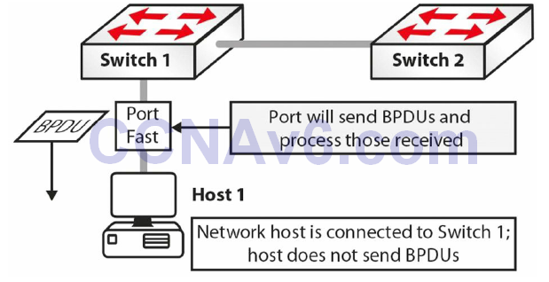
Figure 31.10 – Understanding BPDU Guard
In Figure 31.10, Port Fast is enabled on Switch 1 on its connection to Host 1. Following
initialisation, the port transitions to a Forwarding state, which eliminates 30 seconds of delay that would have been encountered if STA was not bypassed and the port went through the Listening and Learning states. Because the network host is a workstation, it sends no BPDUs on that port.
Either by accident or due to some other malicious intent, Host 1 is disconnected from Switch 1. Using the same port, Switch 3 is connected to Switch 1. Switch 3 is also connected to Switch 2. Because Port Fast is enabled on the port connecting Switch 1 to Switch 3, this port moves from initialisation to the Forwarding state, bypassing normal STP initialisation. This port will also receive and process any BPDUs that are sent by Switch 3, as illustrated in Figure 31.11 below:
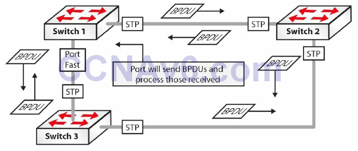
Figure 31.11 – Understanding BPDU Guard (Continued)
Based on the port states illustrated above, you can quickly see how a loop would be created in this network. To prevent this from occurring, BPDU Guard should be enabled on all ports with Port Fast enabled. This is illustrated in Figure 31.12 below:
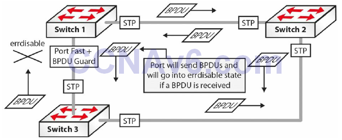
Figure 31.12 – Understanding BPDU Guard (Continued)
With BPDU Guard enabled on the Port Fast port, when Switch 1 receives a BPDU from Switch 3,
it immediately transitions the port into the errdisable state. The result is that the STP calculation is not affected by this redundant link and the network will not have any loops.
BPDU Filter
The BPDU Guard and the BPDU Filter features are often confused or even thought to be the same. They are, however, different, and it is important to understand the differences between them. When Port Fast is enabled on a port, the port will send out BPDUs and will accept and process received BPDUs. The BPDU Guard feature prevents the port from receiving any BPDUs but does not prevent it from sending them. If any BPDUs are received, the port will be errdisabled.
The BPDU Filter feature has dual functionality. When configured at interface level it effectively disables STP on the selected ports by preventing them from sending or receiving any BPDUs. When configured globally and used in conjunction with global Port Fast, it will revert out of Port Fast any port that receives BPDUs. This is illustrated in Figure 31.13 below:
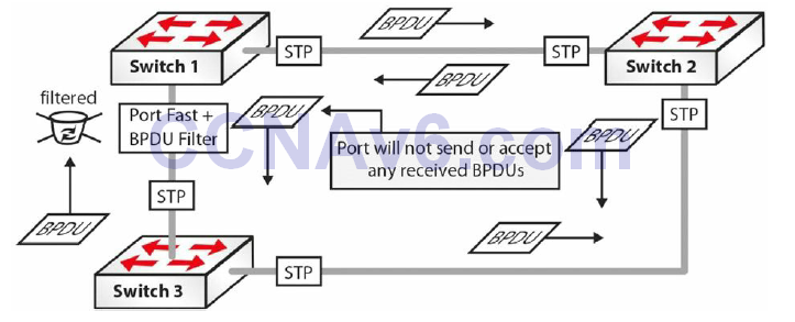
Figure 31.13 – Understanding BPDU Filter
Loop Guard
The Loop Guard feature is used to prevent the formation of loops within the Spanning Tree network. Loop Guard detects Root Ports and blocked ports and ensures that they continue to receive BPDUs. When switches receive BPDUs on blocked ports, the information is ignoredbecause the best BPDU is still being received from the Root Bridge via the Root Port.
If the switch link is up and no BPDUs are received (due to a unidirectional link), the switch assumes that it is safe to bring this link up, and the port transitions to the Forwarding state and begins relaying received BPUDs. If a switch is connected to the other end of the link, this effectively creates a Spanning Tree loop. This concept is illustrated in Figure 31.14 below:
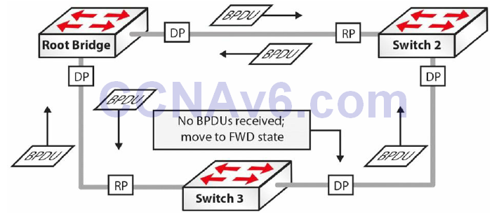
Figure 31.14 – Understanding Loop Guard
In Figure 31.14, the Spanning Tree network has converged and all ports are in a Blocking or Forwarding state. However, the Blocking port on Switch 3 stops receiving BPDUs from the Designated Port on Switch 2 due to a unidirectional link. Switch 3 assumes that the port can be transitioned into a Forwarding state and so begins this move. The switch then relays received BPDUs out of that port, resulting in a network loop.
When Loop Guard is enabled, the switch keeps track of all Non-Designated Ports. As long as the port continues to receive BPDUs, it is fine; however, if the port stops receiving BPDUs, it is moved into a loop-inconsistent state. In other words, when Loop Guard is enabled, the STP port state machine is modified to prevent the port from transitioning from the Non-Designated Port role to the Designated Port role in the absence of BPDUs. When implementing Loop Guard, you should be aware of the following implementation guidelines:
- Loop Guard cannot be enabled on a switch that also has Root Guard enabled
- Loop Guard does not affect Uplink Fast or Backbone Fast operation
- Loop Guard must be enabled on Point-to-Point links only
- Loop Guard operation is not affected by the Spanning Tree timers
- Loop Guard cannot actually detect a unidirectional link
- Loop Guard cannot be enabled on Port Fast or Dynamic VLAN ports
Root Guard
The Root Guard feature prevents a Designated Port from becoming a Root Port. If a port on which the Root Guard feature is enabled receives a superior BPDU, it moves the port into a root-inconsistent state, thus maintaining the current Root Bridge status quo. This concept is illustrated in Figure 31.15 below:
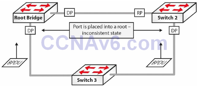
Figure 31.15 – Understanding Root Guard
In Figure 31.15, Switch 3 is added to the current STP network and sends out BPDUs that are superior to those of the current Root Bridge. Under ordinary circumstances, STP would recalculate the entire topology and Switch 3 would be elected the Root Bridge. However, because the Root Guard feature is enabled on the Designated Ports on the current Root Bridge, as well as on Switch 2, both switches will place these ports into a root-inconsistent state when they receive the superior BPDUs from Switch 3. This preserves the Spanning Tree topology.
The Root Guard feature prevents a port from becoming a Root Port, thus ensuring that the port is always a Designated Port. Unlike other STP enhancements, which can also be enabled on a global basis, Root Guard must be manually enabled on all ports where the Root Bridge should not appear. Because of this, it is important to ensure a deterministic topology when designing and implementing STP in the LAN. Root Guard enables an administrator to enforce the Root Bridge placement in the network, ensuring that no customer device inadvertently or otherwise becomes the Root of the Spanning Tree, so it is usually used on the network edge of the ISP towards the customer’s equipment.
Uplink Fast
The Uplink Fast feature provides faster failover to a redundant link when the primary link fails (i.e., direct failure of the Root Port). The primary purpose of this feature is to improve the convergence time of STP in the event of a failure of an uplink. This feature is of most use on Access Layer switches with redundant uplinks to the Distribution Layer; hence, the name.
When Access Layer switches are dual-homed to the Distribution Layer, one of the links is placed into a Blocking state by STP to prevent loops. When the primary link to the Distribution Layer fails, the port in the Blocking state must transition through the Listening and Learning states before it begins forwarding traffic. This results in a 30-second delay before the switch is able to forward frames destined to other network segments. Uplink Fast operation is illustrated in Figure 31.16 below:
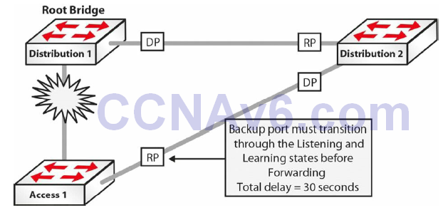
Figure 31.16 – Understanding Uplink Fast
In Figure 31.16, a failure on the link between Access 1 and Distribution 1, which is also the STP Root Bridge, would mean that STP would move the link between Access 1 and Distribution 1 into a Forwarding state (i.e., Blocking > Listening > Learning > Forwarding). The Listening and Learning states take 15 seconds each, so the port would begin to forward frames only after a total of 30 seconds had elapsed. When the Uplink Fast feature is enabled, the backup port to the Distribution Layer is immediately placed into a Forwarding state, resulting in no network downtime. This concept is illustrated in Figure 31.17 below:
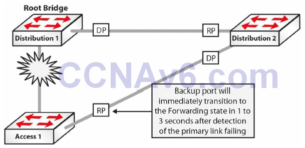
Figure 31.17 – Understanding Uplink Fast (Continued)
Backbone Fast
The Backbone Fast feature provides fast failover when an indirect link failure occurs in the STP domain. Failover occurs when the switch receives an inferior BPDU from its designated bridge (on it’s Root Port). An inferior BPDU indicates that the designated bridge has lost its connection to the Root Bridge, so the switch knows there was an upstream failure and without waiting for timers to expire changes the Root Port. This is illustrated in Figure 31.18 below:
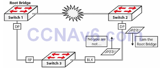
Figure 31.18 – Understanding Backbone Fast
In Figure 31.18, the link between Switch 1 and Switch 2 fails. Switch 2 detects this and sends out BPDUs indicating that it is the Root Bridge. The inferior BPDUs are received on Switch 3, which still has the BPDU information received from Switch 1 saved.
Switch 3 will ignore the inferior BPDUs until the Max Age value expires. During this time, Switch 2 continues to send BPDUs to Switch 3. When the Max Age expires, Switch 3 will age out the stored BPDU information from the Root Bridge and transition into a Listening state, and will then send out the received BPDU from the Root Bridge out to Switch 2.
Because this BPDU is better than its own, Switch 2 stops sending BPDUs, and the port between Switch 2 and Switch 3 transitions through the Listening and Learning states, and, finally, into the Forwarding state. This default method of operation by the STP process will mean that Switch 2 will be unable to forward frames for at least 50 seconds.
The Backbone Fast feature includes a mechanism that allows an immediate check to see whether the BPDU information stored on a port is still valid if an inferior BPDU is received. This is implemented with a new PDU and the Root Link Query (RLQ), which is referred to as the RLQ PDU.
Upon receipt of an inferior BPDU, the switch will send out an RLQ PDU on all Non-Designated Ports, except for the port on which the inferior BPDU was received. If the switch is the Root Bridge or it has lost its connection to the Root Bridge, it will respond to the RLQ. Otherwise, the RLQ will be propagated upstream. If the switch receives an RLQ response on its Root Port, connectivity to the Root Bridge is still intact. If the response is received on a Non-Root Port, it means that connectivity to the Root Bridge is lost, and the local switch Spanning Tree must be recalculated on the switch and the Max Age timer expired so that a new Root Port can be found. This concept is illustrated in Figure 31.19 below:
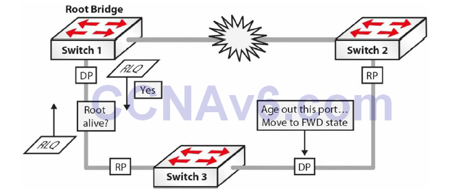
Figure 31.19 – Understanding Backbone Fast (Continued)
Referencing Figure 31.19, upon receipt of the inferior BPDU, Switch 3 sends out an RLQ request on all Non-Designated Ports, except for the port on which the BPDU was received. The Root Bridge responds via an RLQ response sent out of its Designated Port. Because the response is received on the Root Port of Switch 3, it is considered a positive response. However, if the response was received on a Non-Root Port, the response would be considered negative and the switch would need to go through the whole Spanning Tree calculation again.
Based on the positive response received on Switch 3, it can age out the port connected to Switch 2 without waiting for the Max Age timer to expire. The port, however, must still go through the Listening and Learning states. By immediately aging out the Max Age timer, Backbone Fast reduces the convergence time from 50 seconds (20 seconds Max Age + 30 seconds Listening and Learning) to 30 seconds (the time for the Listening and Learning states).
There are two types of RLQs: RLQ requests and RLQ responses. RLQ requests are typically sent out on the Root Port to check for connectivity to the Root Bridge. All RLQ responses are sent out on Designated Ports. Because the RLQ request contains the BID of the Root Bridge that sent it, if another switch in the path to the Root Bridge can still reach the Root Bridge specified in the RLQ response, it will respond back to the sending switch. If this is not the case, the switch simply forwards the query towards the Root Bridge through its Root Port.
NOTE: The RLQ PDU has the same packet format as a normal BPDU, with the only difference being that the RLQ PDU contains two Cisco SNAP addresses that are used for requests and replies.
Troubleshooting STP
Most Layer 2 issues are related to some kind of loop within the domain and this has multiple problems associated with it, including network downtime. When you are working with switch configuration and are plugging/unplugging a device, you should make sure that you aren’t creating a loop in the process. To mitigate against such problems, you should usually configure Spanning Tree Protocol on switches in order to avoid situations that might occur if you happen to accidently create a loop somewhere in the network.
Every switch in a network is communicating using MAC addresses. As packets come in, the MAC address is analysed and the switch determines where that packet goes based on the destination MAC address in the Layer 2 header. Every device in the network has its own MAC address, so all the packets are very specific as to where they are going. Unfortunately, things like Broadcasts and Multicasts go to every port on the switch. If a Broadcast frame arrives at a switch port, it copies that Broadcast to every other device that might be connected to that switch. This process can often be a problem when you have loops in the network.
You should also keep in mind that the MAC address packets have no mechanism inside them to time out. In the case of TCP/IP, the IP protocol has within its header a function called TTL (Time to Live), which refers to the number of hops through a router, not actually to a specific unit of time. So if IP packets happen to be in a loop and are going through multiple routers, they will eventually time out and be removed from the network. On the other hand, switches do not offer that kind of mechanism. Layer 2 frames can theoretically loop forever, as there is no mechanism to time them out, meaning that if you create a loop, it is going to be there until you manually remove it from the network.
If you are plugging in one workstation to the network and a Broadcast reaches it, it will terminate at that point and will not be a problem for the network. On the other hand, if you misconfigure a port configuration on the switch side or you plug both ends into a switch without enabling STP, this might lead to a Broadcast storm within the Layer 2 domain. This happens because Broadcast packets are forwarded to all other ports, so the Broadcast packet keeps exiting and entering the switch on the same cable, causing a Layer 2 loop. This can lead to high resource usage and even network downtime.
If you enable STP on such a misconfigured network, the switch will recognise that a loop has occurred and it would block certain ports to avoid Broadcast storms. Every other port in the switch continues to operate normally, so the network is not affected. If STP is not configured, the only option would be to unplug the network cable that is causing the problem or administratively disable it if you can still operate the switch at that moment.
STP issues usually fall within the following three categories:
- Incorrect Root Bridge
- Incorrect Root Port
- Incorrect Designated Port
Incorrect Root Bridge
Priority and base MAC addresses decide whether the Root Bridge is incorrect. You can issue the show spanning-tree vlan <vlan#> command to see the MAC address and switch priority. You can fix this problem with the spanning-tree vlan <vlan#> priority <priority> command.
Incorrect Root Port
The Root Port provides the fastest path from the switch to the Root Bridge, and the cost is cumulative across the entire path. If you suspect an incorrect Root Port, you can issue the show spanning-tree vlan <vlan#> command. If the Root Port is incorrect, you can issue the spanning-tree cost <cost> command to fix it.
Incorrect Designated Port
The Designated Port is the lowest cost port connecting a network segment to the rest of the network. If you suspect a problem with the Designated Port, you can issue the show spanningtree vlan <vlan#> and spanning-tree cost <cost> commands.
A useful STP troubleshooting command that can debug related events is Switch#debug spanning-tree events.
Section 31 Questions
- How often do switches send Bridge Protocol Data Units ( BPDUs)?
- Name the STP port states in the correct order.
- What is the default Cisco Bridge ID?
- Which command will show you the Root Bridge and priority for a VLAN?
- What is the STP port cost for a 100Mbps link?
- When a port that is configured with the _______ _______ feature receives a BPDU, it immediately transitions to the errdisable state.
- The _______ _______ feature effectively disables STP on the selected ports by preventing them from sending or receiving any BPDUs.
- Which two commands will force the switch to become the Root Bridge for a VLAN?
- Contrary to popular belief, the Port Fast feature does not disable Spanning Tree on the
selected port. This is because even with the Port Fast feature, the port can still send and receive BPDUs. True or false? - The Backbone Fast feature provides fast failover when a direct link failure occurs. Trueor false?
Section 31 Answers
- Every two seconds.
- Blocking, Listening, Learning, Forwarding, and Disabled.
- 32768.
- The show spanning-tree vlan x command.
- 19.
- BPDU Guard.
- BPDU Filter.
- The spanning-tree vlan [number] priority [number] and spanning-tree vlan [number] root [primary|secondary] commands.
- True.
- False.
Section 31 Lab
Spanning Tree Root Selection Lab
Topology

Purpose
Learn how to influence which switch becomes the Spanning Tree Root Bridge.
Walkthrough
1. Set the hostname of each switch and connect them with a crossover cable. You can then
check whether the interface between them is set to “trunk.”
SwitchA#show interface trunk
2. You may not see the trunk link become active until you set one side as a trunk link.
SwitchB#conf t
Enter configuration commands, one per line.  End with CNTL/Z.
SwitchB(config)#int FastEthernet0/1
SwitchB(config-if)#switchport mode trunk
SwitchB(config-if)#^Z
SwitchB#sh int trunk
Port        Mode         Encapsulation  Status        Native vlan
Fa0/1       on           802.1q         trunking      1
Port        Vlans allowed on trunk
Fa0/1       1-1005
Port        Vlans allowed and active in management domain
Fa0/1       1
3. You will see that the other switch is left on auto mode.
SwitchA#show int trunk
Port        Mode         Encapsulation  Status        Native vlan
Fa0/1       auto         n-802.1q       trunking      1
Port        Vlans allowed on trunk
Fa0/1       1-1005
Port        Vlans allowed and active in management domain
Fa0/1       1
4. Create two VLANs on each switch.
SwitchA#conf t
Enter configuration commands, one per line.  End with CNTL/Z.
SwitchA(config)#vlan 2
SwitchA(config-vlan)#vlan 3
SwitchA(config-vlan)#^Z
SwitchA#
%SYS-5-CONFIG_I: Configured from console by console
SwitchA#show vlan brief
VLAN Name                         Status    Ports
---- ------------------           -------   --------------------
1    default                      active    Fa0/2, Fa0/3, Fa0/4,
                                            Fa0/5, Fa0/6, Fa0/7,
                                            Fa0/8, Fa0/9, Fa0/10,
                                            Fa0/11, Fa0/12, Fa0/13,
                                            Fa0/14, Fa0/15, Fa0/16,
                                            Fa0/17, Fa0/18, Fa0/19,
                                            Fa0/20, Fa0/21, Fa0/22,
                                            Fa0/23, Fa0/24
2    VLAN0002                       active
3    VLAN0003                       active
1002 fddi-default                   active
1003 token-ring-default             active
Create the VLANs on Switch B as well (copy the commands above).
5. Determine which switch is the Root Bridge for VLANs 2 and 3.
SwitchB#show spanning-tree vlan 2
VLAN0002
 Spanning tree enabled protocol ieee
 Root ID    Priority    32770
            Address     0001.972A.7A23
            This bridge is the root
            Hello Time  2 sec  Max Age 20 sec  Forward Delay 15 sec
 Bridge ID  Priority    32770  (priority 32768 sys-id-ext 2)
            Address     0001.972A.7A23
            Hello Time  2 sec  Max Age 20 sec  Forward Delay 15 sec
            Aging Time  20
Interface        Role  Sts  Cost      Prio.Nbr Type
---------        ----  ---  ----      -------- ----
Fa0/1            Desg  FWD  19        128.1    P2p
You can see that Switch B is the Root. Do the same command on Switch A and check for VLAN 3. The priority is 32768 plus the VLAN number, which is 2 in this case. The lowest MAC address will then determine the Root Bridge.
SwitchB#show spanning-tree vlan 3
VLAN0003
 Spanning tree enabled protocol ieee
 Root ID    Priority    32771
            Address     0001.972A.7A23
            This bridge is the root
            Hello Time  2 sec  Max Age 20 sec  Forward Delay 15 sec
 Bridge ID  Priority    32771  (priority 32768 sys-id-ext 3)
            Address     0001.972A.7A23
            Hello Time  2 sec  Max Age 20 sec  Forward Delay 15 sec
            Aging Time  20
Interface        Role  Sts  Cost      Prio.Nbr Type
----------       ----  ---  ----      -------- ----
Fa0/1            Desg  FWD  19        128.1    P2p
The MAC address I have for Switch A is higher, which is why it didn’t become the Root Bridge: 0010.1123.D245
6. Set the other switch to be the Root Bridge for VLANs 2 and 3. Use the spanning-tree vlan 2 priority 4096 command for VLAN 2 and the spanning-tree Vlan 3 root primary for VLAN 3.
SwitchA(config)#spanning-tree vlan 2 priority 4096
SwitchA(config)#spanning-tree vlan 3 root primary
SwitchA#show spanning-tree vlan 2
VLAN0002
  Spanning tree enabled protocol ieee
  Root ID    Priority    4098
             Address     0010.1123.D245
             This bridge is the root
             Hello Time  2 sec  Max Age 20 sec  Forward Delay 15 sec
  Bridge ID  Priority    4098  (priority 4096 sys-id-ext 2)
             Address     0010.1123.D245
             Hello Time  2 sec  Max Age 20 sec  Forward Delay 15 sec
             Aging Time  20
Interface        Role  Sts  Cost      Prio.Nbr Type
---------        ----  ---  ----      -------- ----Fa0/1            Desg  FWD  19        128.1    P2p
SwitchA#show spanning-tree vlan 3
VLAN0003
  Spanning tree enabled protocol ieee
  Root ID    Priority    24579
             Address     0010.1123.D245
             This bridge is the root
             Hello Time  2 sec  Max Age 20 sec  Forward Delay 15 sec
  Bridge ID  Priority    24579  (priority 24576 sys-id-ext 3)
             Address     0010.1123.D245
             Hello Time  2 sec  Max Age 20 sec  Forward Delay 15 sec
             Aging Time  20
Interface        Role  Sts  Cost      Prio.Nbr Type
---------        ----  ---  ----      -------- ----
Fa0/1            Desg  FWD  19        128.1    P2p
SwitchA#
NOTE: Despite Switch B having the lower Bridge ID, Switch A was forced to be the Root Bridge.
