11.2.4 Packet Tracer – Configuring Interfaces Answers
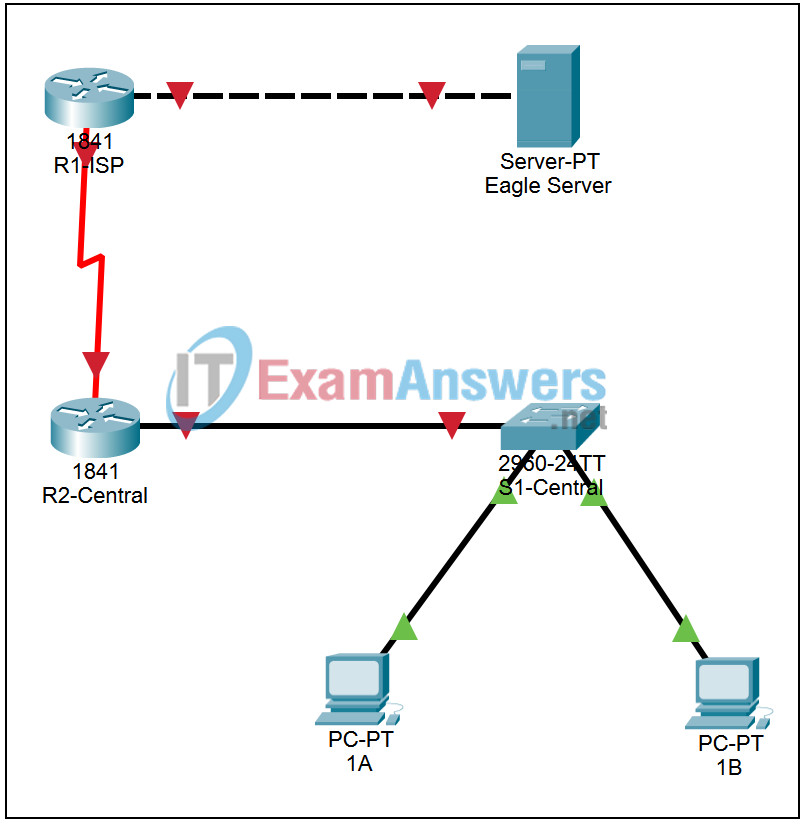
Topology

| Device | Interface | IP Address | Subnet Mask | Default Gateway |
|---|---|---|---|---|
| R1-ISP | Fa0/0 | 192.168.254.253 | 255.255.255.0 | N/A |
| S0/0/0 | 10.10.10.6 | 255.255.255.252 | ||
| R2-Central | Fa0/0 | 172.16.255.254 | 255.255.255.0 | N/A |
| S0/0/0 | 10.10.10.5 | 255.255.255.252 | ||
| S1-Central | VLAN 1 | 172.16.254.1 | 255.255.0.0 | 172.16.255.254 |
| PC 1A | NIC | 172.16.1.1 | 255.255.0.0 | 172.16.255.254 |
| PC 1B | NIC | 172.16.1.2 | 255.255.0.0 | 172.16.255.254 |
| Eagle Server | NIC | 192.168.254.254 | 255.255.255.0 | 192.168.254.253 |
Learning Objectives
Configuring interfaces on routers and switches
Introduction:
In this activity we will configure IP information and descriptions on the routers and switch in the standard lab topology.
Task 1: Configuring interfaces on routers and switches
Step 1. Configuring interfaces on a router
Click on router R1-ISP. Log in to the router using the CLI tab with password cisco. Enter privileged EXEC mode with password class. Enter global configuration mode.
Enter the command interface fa0/0 to enter interface configuration mode for the FastEthernet interface. Notice the change in the prompt. Enter the command ip address 192.168.254.253 255.255.255.0 to set the IP address and subnet mask. Enter the command description Link to Eagle Server to describe the interface. Enter the command no shutdown to enable the interface. Enter the command exit to return to global configuration mode.
Enter the command interface s0/0/0 to enter interface configuration mode for the serial interface. Enter the command ip address 10.10.10.6 255.255.255.252 to set the IP address and subnet mask. This interface is where the DCE end of the serial cross-over cable connects. Enter the command clock rate 64000 to set the interface to supply a timing signal. Enter the command description Link to R2-Central to describe the interface. Enter the command no shutdown to enable the interface. Enter the command exit to return to global configuration mode.
Press Ctrl+z to leave configuration mode. Enter the command copy running-config startup-config to save your changes to NVRAM. Press Enter at the prompt to confirm the destination filename.
Verify the configuration by entering the commands show running-config and show interfaces.
Step 2. Configuring interfaces on the other router
Repeat Step 1 to configure and verify the interfaces on router R2-Central using the information in the table above. Note that the serial interface on router R2-Central is connected to the DTE end of the serial cross-over cable. Use descriptions “Link to S1-Central” and “Link to R1-ISP” as appropriate.
Step 3. Configuring an interface on a switch
Click on switch S1-Central. Log in to the switch using the CLI tab with password cisco. Enter privileged EXEC mode with password class. Enter global configuration mode.Enter the command interface vlan 1 to enter interface configuration mode for the management vlan interface. Notice the change in the prompt. Enter the command ip address 172.16.254.1 255.255.0.0 to set the IP address and subnet mask. Enter the command no shutdown to enable the interface. Enter the command exit to return to global configuration mode. Enter the command ip default-gateway 172.16.255.254 to set the address to use to reach devices that are not in the local subnet.
Press Ctrl+z to leave configuration mode. Enter the command copy running-config startup-config to save your changes to NVRAM. Press Enter at the prompt to confirm the destination filename.
Verify the configuration by entering the command show running-config.
NOTE: Hostnames, Passwords, Banners, Descriptions are CaSe-SensiTiVe
