Objectives
Upon completion of this chapter, you will be able to answer the following questions:
- What is the basic operation of data network communications?
- How do protocols enable network operations?
- How does Ethernet support network communication?
- How does the IPv4 protocol support network communications?
- How do IP addresses enable network communication?
- Which type of IPv4 addresses enable network communication?
- How does the default gateway enable network communications?
- How does the IPv6 protocol support network communications?
- How is ICMP used to test network connectivity?
- How do you use ping and traceroute utilities to test network connectivity?
- What are the roles of the MAC address and the IP address?
- What is the purpose of ARP?
- How do ARP requests impact network and host performance?
- How do transport layer protocols support network communication?
- How do the transport layer protocols operate?
- How do DHCP services enable network functionality?
- How do DNS services enable network functionality?
- How do NAT services enable network functionality?
- How do file transfer services enable network functionality?
- How do email services enable network functionality?
- How do HTTP services enable network functionality?
Key Terms
This chapter uses the following key terms. You can find the definitions in the Glossary.
network protocols
protocol suite
TCP/IP protocol suite
Domain Name System (DNS)
Bootstrap Protocol (BOOTP)
Dynamic Host Configuration Protocol (DHCP)
Simple Mail Transfer Protocol (SMTP)
Post Office Protocol version 3 (POP3)
Internet Message Access Protocol (IMAP)
File Transfer Protocol (FTP)
Trivial File Transfer Protocol (TFTP)
Hypertext Transfer Protocol (HTTP)
User Datagram Protocol (UDP)
Transmission Control Protocol (TCP)
Internet Protocol (IP)
Network Address Translation (NAT)
Internet Control Message Protocol (ICMP)
Open Shortest Path First (OSPF)
Enhanced Interior Gateway Routing Protocol (EIGRP)
Address Resolution Protocol (ARP)
Point-to-Point Protocol (PPP)
Ethernet
unicast
multicast
broadcast
Open Systems Interconnection (OSI) model
Application layer
Presentation layer
Session layer
Transport layer
Network layer
Data Link layer
Physical layer
segmentation
multiplexing
protocol data unit (PDU)
Logical Link Control (LLC) sublayer
Media Access Control (MAC) sublayer
connectionless
unreliable
maximum transmission unit (MTU)
octet page 148dotted-decimal
subnetting
public IPv4 address
private IPv4 address
subnet mask
default gateway
hextet
Time to Live (TTL)
Neighbor Discovery Protocol (ND or NDP)
Router Solicitation (RS)
Router Advertisement (RA)
Neighbor Solicitation (NS)
Neighbor Advertisement (NA)
Stateless Address Autoconfiguration (SLAAC)
Duplicate Address Detection (DAD)
ping
traceroute
round-trip time (RTT)
ARP spoofing
source port
destination port
socket
flow control
window size
resolver
recursion
authoritative server
recursive resolver
fully qualified domain name (FQDN)
resource record (RR)
DNS Zone
Dynamic DNS (DDNS)
WHOIS
Port Address Translation (PAT)
Server Message Block (SMB)
Introduction (4.0)
Cybersecurity analysts work to identify and analyze the traces of network security incidents. These traces consist of records of network events. These events, recorded in log files from various devices, are primarily composed of details of network protocol operations. Addresses identify which hosts connected to each other, within an organization, or to distant hosts on the Internet. Addresses held in log files also identify which hosts connected with, or attempted to connect with, hosts within an organization. Other traces, in the form of protocol addresses, identify what the network connections attempted to do, and whether this behavior was normal, suspicious, or damaging. Finally, network traces are recorded for the applications that enable us to receive and use information from the network. From all of these traces, cybersecurity analysts detect threats to the security of organizations and their data.
Cybersecurity analysts must understand the network on which normal data travels so that they can detect the abnormal behavior that is created by hackers, malevolent software, and dishonest users of the network. Protocols are at the heart of network communications, and network services support the tasks that we perform using the network. This chapter provides an overview of how networks normally behave through a discussion of the protocols in the TCP/IP suite of protocols, and associated services that enable us to accomplish tasks on computer networks.
Network Protocols (4.1)
In this section, you will learn how protocols enable network operations.
Network Communications Process (4.1.1)
In this topic, you will learn the basic operation of data network communications.
Views of the Network (4.1.1.1)
Networks come in all sizes. They can range from simple networks consisting of two computers to networks connecting millions of devices.
Home office networks and small office networks are often set up by individuals that work from a home or a remote office and need to connect to a corporate network or other centralized resources. Additionally, many self-employed entrepreneurs use home office and small office networks to advertise and sell products, order supplies and communicate with customers.
In businesses and large organizations, networks can be used on an even broader scale to provide consolidation, storage, and access to information on network servers. Networks also allow for rapid communication such as email, instant messaging, and collaboration among employees. In addition to internal benefits, many organizations use their networks to provide products and services to customers through their connection to the Internet.
The Internet is the largest network in existence. In fact, the term Internet means a “network of networks.” The Internet is literally a collection of interconnected private and public networks.
Client-Server Communications (4.1.1.2)
All computers that are connected to a network and that participate directly in network communication are classified as hosts. Hosts are also called end devices, endpoints, or nodes. Much of the interaction between end devices is client-server traffic. For example, when you access a web page on the Internet, your web browser (the client) is accessing a server. When you send an email message, your email client will connect to an email server.
Servers are simply computers with specialized software. This software enables servers to provide information to other end devices on the network. A server canbe single-purpose, providing only one service, such as web pages. A server can be multipurpose, providing a variety of services such as web pages, email, and file transfers.
Client computers have software installed, such as web browsers, email, and file transfer applications. This software enables them to request and display the information obtained from the server. A single computer can also run multiple types of client software. For example, a user can check email and view a web page while listening to Internet radio.
A Typical Session: Student (4.1.1.3)
A typical network user at school, at home, or in the office will normally use some type of computing device to establish many connections with network servers. Those servers could be located in the same room or around the world. Let’s look at a few typical network communication sessions.
Terry is a high school student whose school has recently started a “bring your own device” (BYOD) program. Students are encouraged to use their cell phones or other devices such as tablets or laptops to access learning resources. Terry has just been given an assignment in language arts class to research the effects of World War I on the literature and art of the time. She enters the search terms she has chosen into a search engine app that she has opened on her cell phone.
Terry has connected her phone to the school Wi-Fi network. Her search is submitted from her phone to the school network wirelessly. Before her search can be sent, the data must be addressed so that it can find its way back to Terry. Her search terms are then represented as a string of binary data that has been encoded into radio waves. Her search string is then converted to electrical signals that travel on the school’s wired network until they reach the place at which the school’s network connects to the Internet service provider’s (ISP) network. A combination of technologies take Terry’s search to the search engine website.
For example, Terry’s data flows with the data of thousands of other users along a fiber-optic network that connects Terry’s ISP with the several other ISPs, including the ISP that is used by the search engine company. Eventually, Terry’s search string enters the search engine company’s website and is processed by its powerful servers. The results are then encoded and addressed to Terry’s school and her device.
All of these transitions and connections happen in a fraction of a second, and Terry has started on her path to learning about her subject.
A Typical Session: Gamer (4.1.1.4)
Michelle loves computer games. She has a powerful gaming console that she uses to play games against other players, watch movies, and play music. Michelle connects her game console directly to her network with a copper network cable.
Michelle’s network, like many home networks, connects to an ISP using a router and modem. These devices allow Michelle’s home network to connect to a cable TV network that belongs to Michelle’s ISP. The cable wires for Michelle’s neighborhood all connect to a central point on a telephone pole and then connect to a fiber-optic network. This fiber-optic network connects many neighborhoods that are served by Michelle’s ISP.
All those fiber-optic cables connect to telecommunications services that provide access to the high-capacity connections. These connections allow thousands of users in homes, government offices, and businesses to connect Internet destinations around the world.
Michelle has connected her game console to a company that hosts a very popular online game. Michelle is registered with the company, and its servers keep track of Michelle’s scores, experiences, and game assets. Michelle’s actions in her game become data that is sent to the gamer network. Michelle’s moves are broken up to groups of binary data that each consist of a string of zeros and ones. Information that identifies Michelle, the game she is playing, and Michelle’s network location are added to the game data. The pieces of data that represent Michelle’s game play are sent at high speed to the game provider’s network. The results are returned to Michelle in the form of graphics and sounds.
All of this happens so quickly that Michelle can compete with hundreds of other gamers in real time.
A Typical Session: Surgeon (4.1.1.5)
Dr. Ismael Awad is an oncologist who performs surgery on cancer patients. He frequently needs to consult with radiologists and other specialists on patient cases. The hospital that Dr. Awad works for subscribes to a special service calleda cloud. The cloud allows medical data, including patient X-rays and MRIs, to be stored in a central location that is accessed over the Internet. In this way, the hospital does not need to manage paper patient records and X-ray films.
When a patient has an X-ray taken, the image is digitized as computer data. The X-ray is then prepared by hospital computers to be sent to the medical cloud service. Because security is very important when working with medical data, the hospital uses network services that encrypt the image data and patient information. This encrypted data cannot be intercepted and read as it travels across the Internet to the cloud service provider’s data centers. The data is addressed so that it can be routed to the cloud provider’s data center to reach the correct services that provide storage and retrieval of high-resolution digital images.
Dr. Awad and the patient’s care team can connect to this special service, meet with other doctors in audio conferences, and discuss patient records to decide on the best treatment that can be provided to the patient. Dr. Awad can work with specialists from diverse locations to view the medical images and other patient data and discuss the case.
All of this interaction is digital and takes place using networked services that are provided by the medical cloud service.
Tracing the Path (4.1.1.6)
We tend to think about the data networks we use in our daily lives as we think about driving a car. We do not really care what happens in the engine as long as the car takes us where we want to go. However, just like a car’s mechanic knows the details of how a car operates, cybersecurity analysts need to have a deep understanding of how networks operate.
When we connect to a website to read social media or shop, we seldom care about how our data gets to the website and how data from the website gets to us. We are not aware of the many technologies that enable us to use the Internet. A combination of copper and fiber-optic cables that go over land and under the ocean carry data traffic. High-speed wireless and satellite technologies are also used. These connections connect telecommunications facilities and ISPs that are distributed throughout the world, as shown in Figure 4-1.
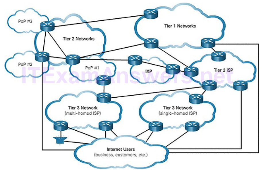
Figure 4-1 Tracing the Path
These global Tier 1 and Tier 2 ISPs connect portions of the Internet together, usually through an Internet Exchange Point (IXP). Larger networks will connect to Tier 2 networks through a Point of Presence (PoP), which is usually a location in the building where physical connections to the ISP are made. The Tier 3 ISPs connect homes and businesses to the Internet.
Because of different relationships between ISPs and telecommunications companies, traffic from a computer to an Internet server can take many paths. The traffic of a user in one country can take a very indirect path to reach its destination. The traffic might first travel from the local ISP to a facility that has connections to many other ISPs. A user’s Internet traffic can go many hundreds of miles in one direction only to be routed in a completely different direction to reach its destination. Some of the traffic can take certain routes to reach the destination, and then take completely different routes to return.
Cybersecurity analysts must be able to determine the origin of traffic that enters the network, and the destination of traffic that leaves it. Understanding the path that network traffic takes is essential to this.
In this lab, you will use two route tracing utilities to examine the Internet pathway to destination networks. First, you will verify connectivity to a website. Second, you will use the traceroute utility on the Linux command line. Third, you will use a web-based traceroute tool.
Communications Protocols (4.1.2)
In this topic, you will learn how protocols enable network operations.
What Are Protocols? (4.1.2.1)
Simply having a wired or wireless physical connection between end devices is not enough to enable communication. For communication to occur, devices must know “how” to communicate. Communication, whether by face-to-face or over a network, is governed by rules called protocols. These protocols are specific to the type of communication method occurring.
For example, consider two people communicating face-to-face. Prior to communicating, they must agree on how to communicate. If the communication is using voice, they must first agree on the language. Next, when they have a message to share, they must be able to format that message in a way that is understandable. For example, if someone uses the English language but poor sentence structure, the message can easily be misunderstood.
Network protocol communication is the same way. Network protocols provide the means for computers to communicate on networks. Network protocols dictate the message encoding, formatting, encapsulation, size, timing, and delivery options, as shown in Figure 4-2. As a cybersecurity analyst, you must be very familiar with structure of protocols and how they are used in network communications.
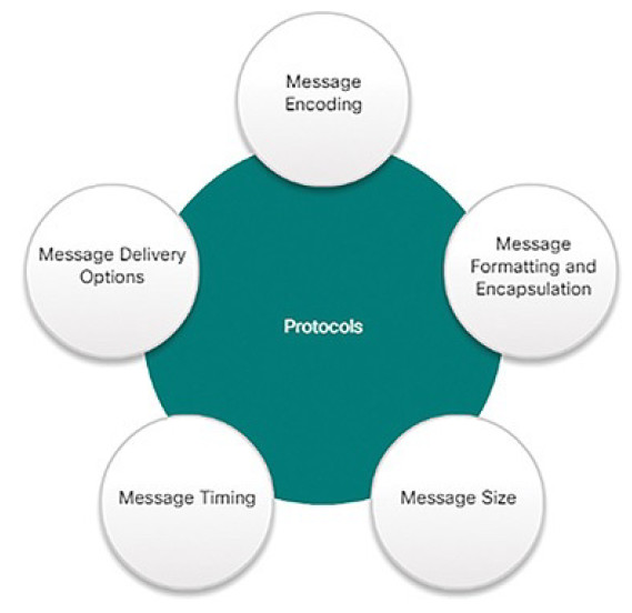
Figure 4-2 Network Protocol Characteristics
Network Protocol Suites (4.1.2.2)
A protocol suite is a set of protocols that work together to provide comprehensive network communication services. A protocol suite may be specified by a standards organization or developed by a vendor.
For devices to successfully communicate, a network protocol suite must describe precise requirements and interactions. Networking protocols define a common format and set of rules for exchanging messages between devices. Some common networking protocols are Hypertext Transfer Protocol (HTTP), Transmission Control Protocol (TCP), and Internet Protocol (IP).
Note
IP in this course refers to both the IPv4 and IPv6 protocols. IPv6 is the most recent version of IP and will eventually replace the more common IPv4.
Figures 4-3 through 4-6 illustrate the role of networking protocols:
How the message is formatted or structured, as shown in Figure 4-3
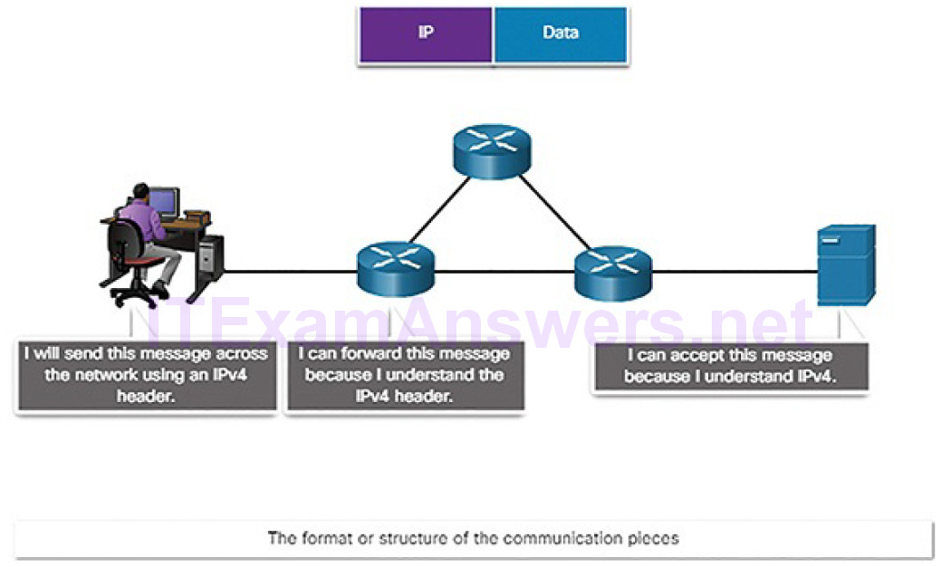
Figure 4-3 The Role of Protocols: Format and Structure
The process by which networking devices share information about pathways with other networks, as shown in Figure 4-4
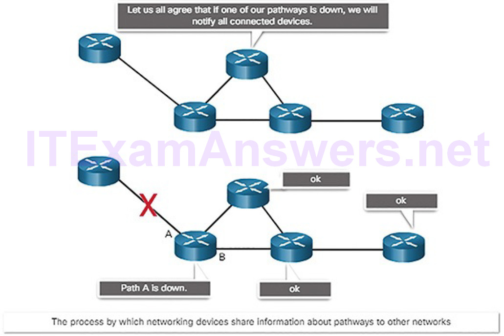
Figure 4-4 The Role of Protocols: Routers Sharing Path Information
How and when error and system messages are passed between devices, as shown in Figure 4-5
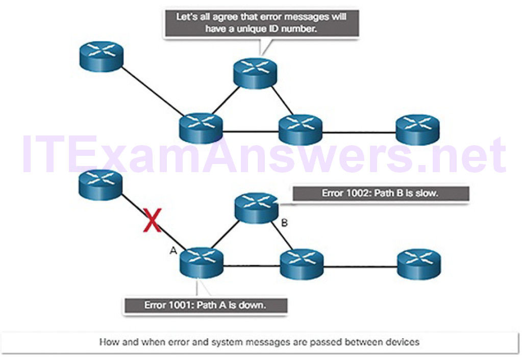
Figure 4-5 The Role of Protocols: Error Messages
The setup and termination of data transfer sessions, as shown in Figure 4-6
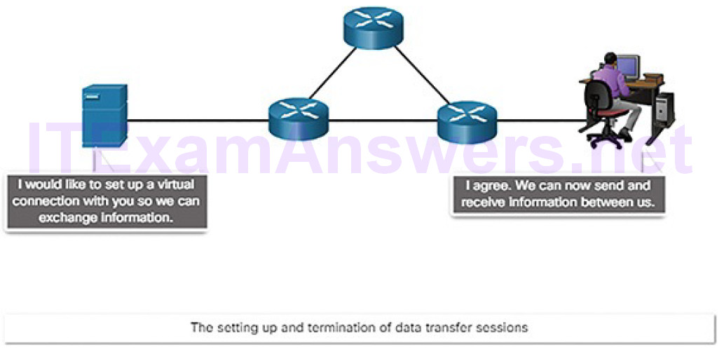
Figure 4-6 The Role of Protocols: Session Setup and Termination
The TCP/IP Protocol Suite (4.1.2.3)
Networks today use the TCP/IP protocol suite. Figure 4-7 shows the protocols of the TCP/IP protocol suite.
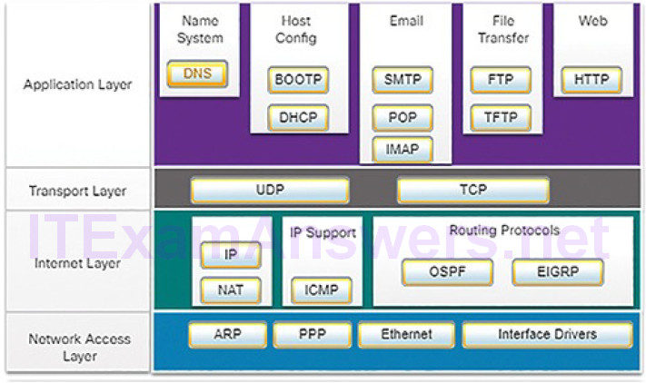
Figure 4-7 TCP/IP Protocol Suite and Communication Process
Table 4-1 lists a description of each protocol shown in Figure 4-7.
Table 4-1 TCP/IP Protocols and Standards Descriptions
| Name | Acronym | Description |
|---|---|---|
| Domain Name System | DNS | Translates domain names, such as cisco.com, into IP addresses. |
| Bootstrap Protocol | BOOTP | Enables a diskless workstation to discover its own IP address, the IP address of a BOOTP server on the network, and a file to be loaded into memory to boot the machine. BOOTP is being superseded by DHCP. |
| Dynamic Host Configuration Protocol | DHCP | Dynamically assigns IP addresses to client stations at startup. Allows the addresses to be reused when no longer needed. |
| Simple Mail Transfer Protocol | SMTP | Enables clients to send email to a mail server. Enables servers to send email to other servers. |
| Post Office Protocol version 3 | POP3 | Enables clients to retrieve email from a mail server. Downloads email from the mail server to the desktop. |
| Internet Message Access Protocol | IMAP | Enables clients to access email stored on a mail server. Maintains email on the server. |
| File Transfer Protocol | FTP | Sets rules that enable a user on one host to access and transfer files to and from another host over a network. A reliable, connection-oriented, and acknowledged file delivery protocol. |
| Trivial File Transfer Protocol | TFTP | A simple, connectionless file transfer protocol. A best-effort, unacknowledged file delivery protocol. Utilizes less overhead than FTP. |
| Hypertext Transfer Protocol | HTTP | Set of rules for exchanging text, graphic images, sound, video, and other multimedia files on the World Wide Web. |
| User Datagram Protocol | UDP | Enables a process running on one host to send packets to a process running on another host. Does not confirm successful datagram transmission. |
| Transmission Control Protocol | TCP | Enables reliable communication between processes running on separate hosts. Reliable, acknowledged transmissions that confirm successful delivery. |
| Internet Protocol | IP | Receives message segments from the transport layer. Packages messages into packets. Addresses packets for end-to-end delivery over an Internetwork. |
| Network Address Translation | NAT | Translates IP addresses from a private network into globally unique public IP addresses. |
| Internet Control Message Protocol | ICMP | Provides feedback from a destination host to a source host about errors in packet delivery. |
| Open Shortest Path First | OSPF | Link-state routing protocol. Hierarchical design based on areas. Open standard interior routing protocol. |
| Enhanced Interior Gateway Routing Protocol | EIGRP | Cisco proprietary routing protocol. Uses composite metric based on bandwidth, delay, load, and reliability. |
| Address Resolution Protocol | ARP | Provides dynamic address mapping between an IP address and a hardware address. |
| Point-to-Point Protocol | PPP | Provides a means of encapsulating packets for transmission over a serial link. |
| Ethernet | Defines the rules for wiring and signaling standards of the network access layer. | |
| Interface | Provides instruction to a machine for the control of a | |
| Drivers | specific interface on a network device. |
The individual protocols are organized in layers using the TCP/IP protocol model: Application, Transport, Internet, and Network Access Layers. TCP/IP protocols are specific to the Application, Transport, and Internet layers. The network access layer protocols are responsible for delivering the IP packet over the physical medium, such as through a network cable or wireless signal.
The TCP/IP protocol suite is implemented on both the sending and receiving hosts to provide end-to-end delivery of messages over a network. TCP/IP has standardized the way the computers communicate, which has enabled the Internet as we know it today. Unfortunately, this widespread usage has attracted the attention of people who want to misuse networks. Much of the work of the cybersecurity analyst concerns analysis of the behavior of the TCP/IP suite of protocols.
Format, Size, and Timing (4.1.2.4)
Protocols define the format, size, and timing of different forms of messages.
Format
When you send an email, protocols of the TCP/IP protocol suite are used by your device to format your message for sending on the network. This is similar to you sending a letter in the mail. You place your letter in an envelope. The envelope has the address of the sender and receiver, each located at the proper place on the envelope. If the destination address and formatting are not correct, the letter is not delivered. The process of placing one message format (the letter) inside another message format (the envelope) is called encapsulation. De-encapsulation occurs when the process is reversed by the recipient and the letter is removed from the envelope.
Just as a letter is encapsulated in an envelope for delivery, so too are computer messages encapsulated. Each computer message is encapsulated in a specific format, called a frame, before it is sent over the network. The frame structure is discussed later in the chapter.
Size
Another rule of communication is size. When people communicate in person or over the phone, a conversation is usually made up of many smaller sentences to ensure that each part of the message is received and understood.
Likewise, when a long message is sent from one host to another over a network, it is necessary to break the message into many frames, as shown in Figure 4-8. Each frame will have its own addressing information. At the receiving host, the individual frames are reconstructed into the original message.
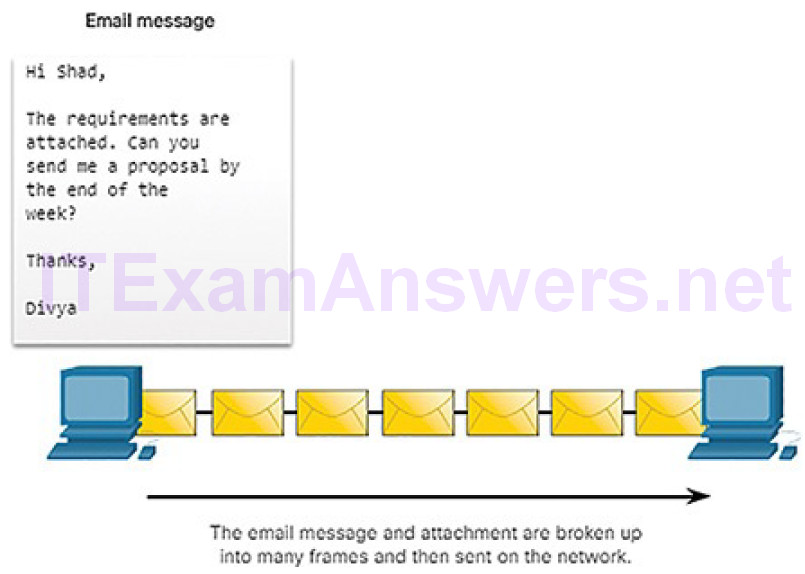
Figure 4-8 Breaking Up a Message
Timing
Timing includes the access method (when can a host send), flow control (how much information can a host send at one time), and response timeout (how long to wait for a response). This chapter will explore how network protocols manage these timing issues.
Unicast, Multicast, and Broadcast (4.1.2.5)
A message can be delivered in different ways. Sometimes, a person wants to communicate information to a single individual. At other times, the person may need to send information to a group of people at the same time, or even to allpeople in the same area.
Hosts on a network use similar delivery options to communicate.
A one-to-one delivery option is referred to as a unicast, meaning there is only a single destination for the message, as shown in Figure 4-9.
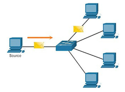
Figure 4-9 Unicast Message
When a host needs to send messages using a one-to-many delivery option, it is referred to as a multicast, as shown in Figure 4-10.
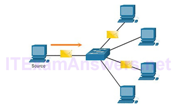
Figure 4-10 Multicast Message
If all hosts on the network need to receive the message at the same time, a broadcast may be used. Broadcasting represents a one-to-all message delivery option, as shown in Figure 4-11.
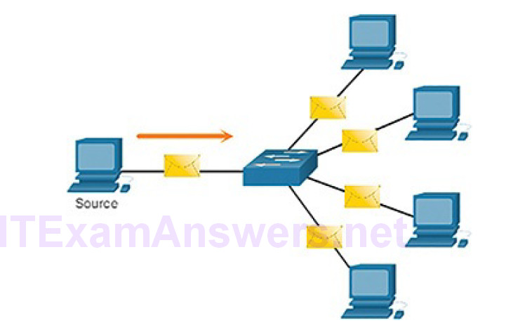
Figure 4-11 Broadcast Message
Reference Models (4.1.2.6)
As you learned earlier, the TCP/IP protocol suite is represented by a four-layer model: Application, Transport, Internet, and Network Access. Another popular reference model is the Open Systems Interconnection (OSI) model, which uses a seven-layer model, as shown Figure 4-12. In networking literature, when a layer is referred to by a number, such as Layer 4, then the reference is using the Open Systems Interconnection (OSI) model. Reference to layers in the TCP/IP model use the name of the layer, such as the transport layer.
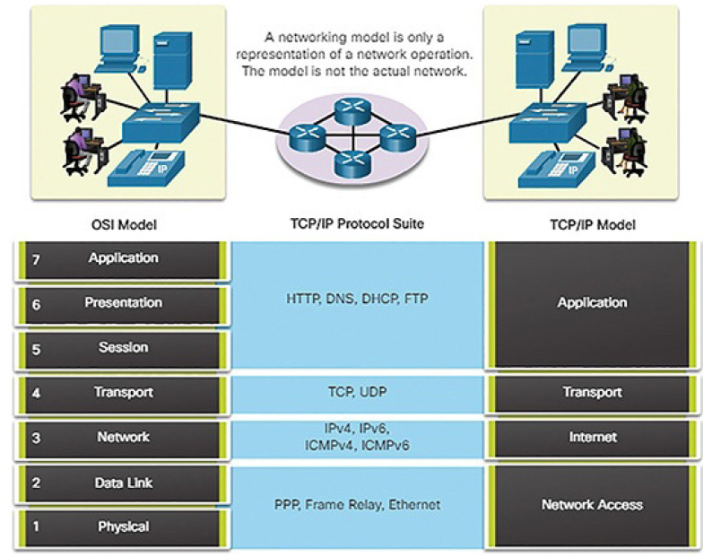
Figure 4-12 Comparing the OSI and TCP/IP Models
The OSI Reference Model
The OSI model provides an extensive list of functions and services that can occur at each layer. It also describes the interaction of each layer with the layers directly above and below. Table 4-2 describes each layer of the OSI model.
Table 4-2 Layers of the OSI Model
| Number | Layer Name | Description |
|---|---|---|
| 7 | Application | The application layer contains protocols used for process-to-process communications. |
| 6 | Presentation | The presentation layer provides for common representation of the data transferred between application layer services. |
| 5 | Session | The session layer provides services to the presentation layer to organize its dialogue and to manage data exchange. |
| 4 | Transport | The transport layer defines services to segment, transfer, and reassemble the data for individual communications between the end devices. |
| 3 | Network | The network layer provides services to exchange the individual pieces of data over the network between identified end devices. |
| 2 | Data Link | The data link layer protocols describe methods for exchanging data frames between devices over a common media. |
| 1 | Physical | The physical layer protocols describe the mechanical, electrical, functional, and procedural means to activate, maintain, and deactivate physical connections for bit transmission to and from a network device. |
The TCP/IP Protocol Model
The TCP/IP protocol model for internetwork communications was created in the early 1970s. As shown in Figure 4-13, it defines four categories of functions that must occur for communications to be successful.
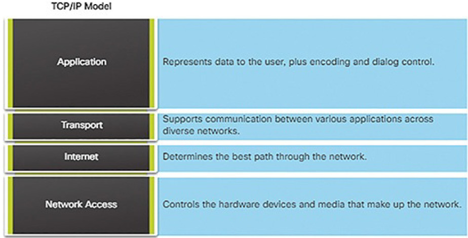
Figure 4-13 Layers of the TCP/IP Model
Three Addresses (4.1.2.7)
Network protocols require that addresses be used for network communication.
Addressing is used by the client to send requests and other data to a server. The server uses the client’s address to return the requested data to the client that requested it.
Protocols operate at layers. The OSI transport, network, and data link layers all use addressing in some form. The transport layer uses protocol addresses in the form of port numbers to identify network applications that should handle client and server data. The network layer specifies addresses that identify the networks that clients and servers are attached to and the clients and servers themselves.
Finally, the data link layer specifies the devices on the local LAN that should handle data frames. All three addresses are required for client-server communication, as shown in Figure 4-14.
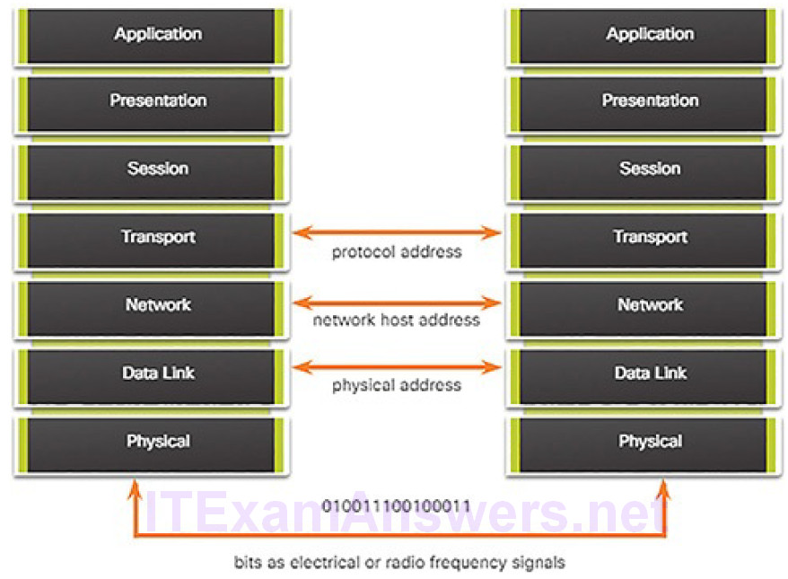
Figure 4-14 The Three Addresses and Layers
Encapsulation (4.1.2.8)
As you have seen, data is divided into smaller, more manageable pieces to send over the network. This division of data into smaller pieces is called segmentation. Segmenting messages has two primary benefits:
Segmentation (Figure 4-15): This process increases the efficiency of network communications. If part of the message fails to make it to the destination, due to failure in the network or network congestion, only the missing parts need to be retransmitted.
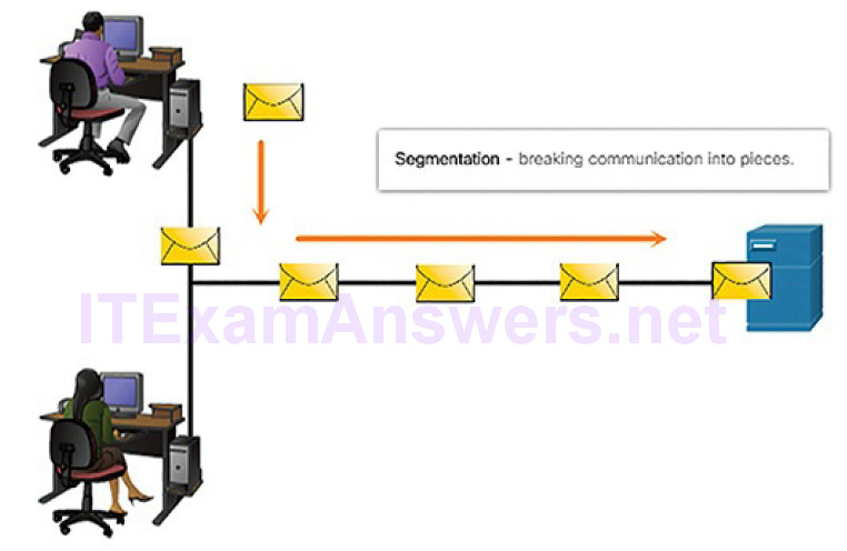
Figure 4-15 Message Segmentation
Multiplexing (Figure 4-16): By sending smaller individual pieces from source to destination, many different conversations can be interleaved on the network. This is called multiplexing.
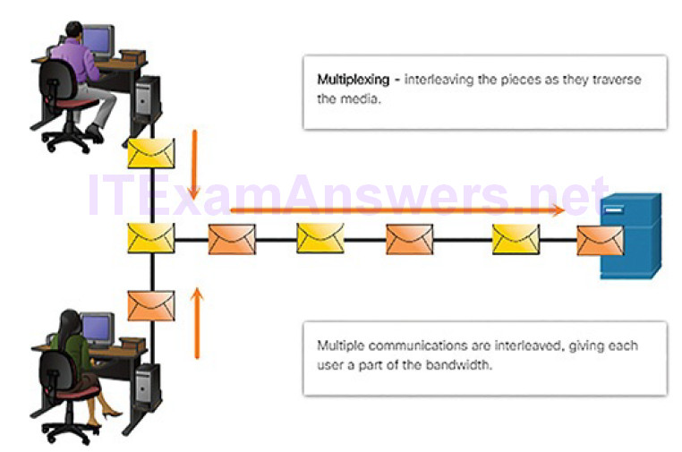
Figure 4-17 Labeling the Message
As application data is passed down the protocol stack on its way to be transmitted across the network media, it is encapsulated with various protocol information at each level.
The form that an encapsulated piece of data takes at any layer is called a protocol data unit (PDU). Each succeeding layer encapsulates the PDU that it receives from the layer above in accordance with the protocol being used. At each stage of the process, a PDU has a different name to reflect its new functions. Although there is no universal naming convention for PDUs, in this course, the PDUs are named according to the protocols of the TCP/IP suite, as shown in the Figure 4-18.
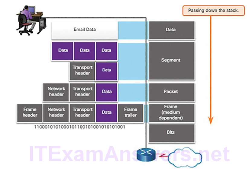
Figure 4-18 Encapsulation Down the Layers
When sending messages on a network, the encapsulation process works from top to bottom. At each layer, the upper layer information is considered data within the encapsulated protocol. For example, the TCP segment is considered data within the IP packet. Figures 4-19 through 4-23 demonstrate the encapsulation process as a web server sends a web page to a web client.
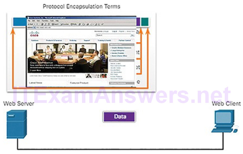
Figure 4-19 Encapsulation: Data
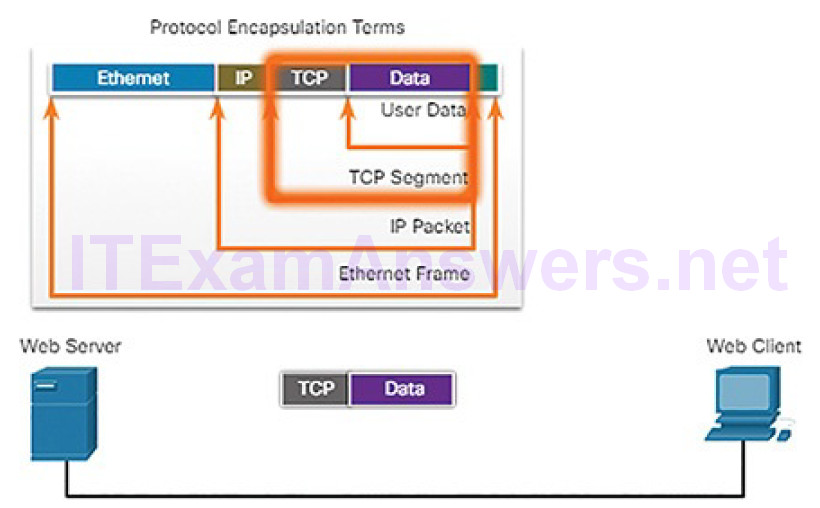
Figure 4-20 Encapsulation: TCP
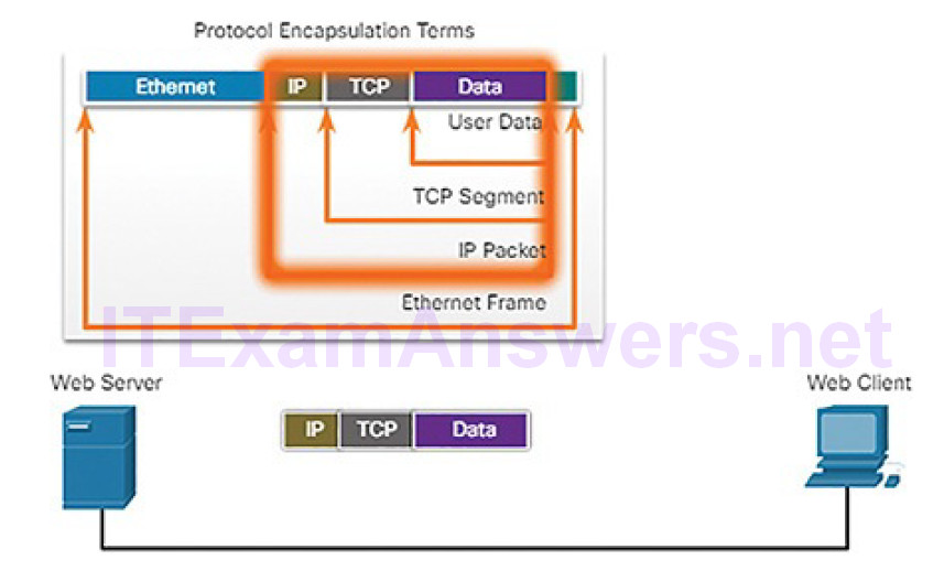
Figure 4-21 Encapsulation: IP
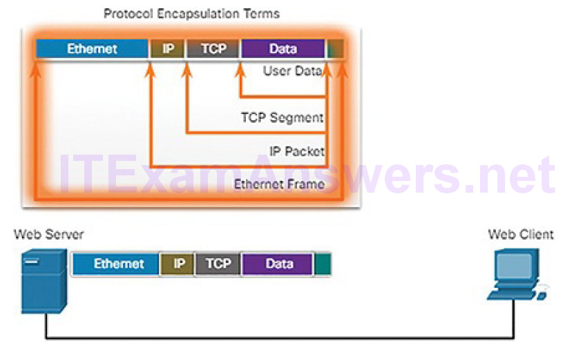
Figure 4-22 Encapsulation: Ethernet
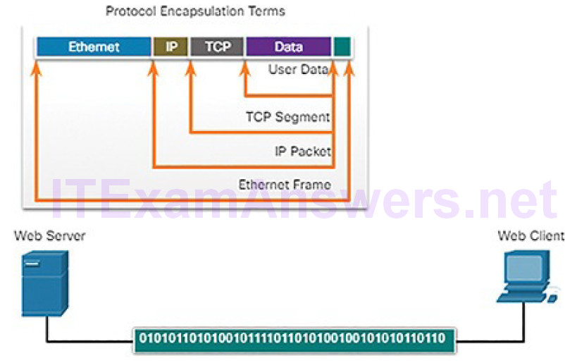
Figure 4-23 Encapsulation: Bits
Messages sent across the network are first converted into bits by the sending host. Each bit is encoded into a pattern of sounds, light waves, or electrical impulses depending on the network media over which the bits are transmitted. The destination host receives and decodes the signals in order to interpret the message.
This process is reversed at the receiving host, and is known as de-encapsulation.
The data is de-encapsulated as it moves up the stack toward the end-user application. Figures 4-24 and 4-25 demonstrate the de-encapsulation process.
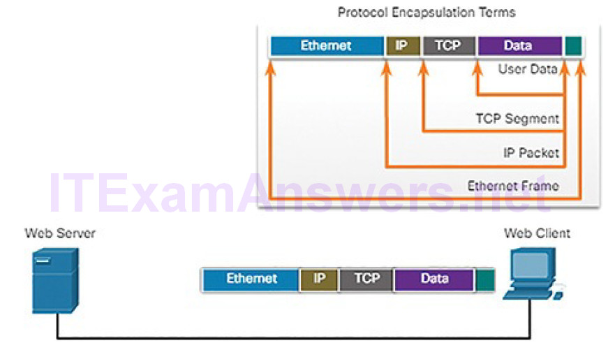
Figure 4-24 Receiving the Message
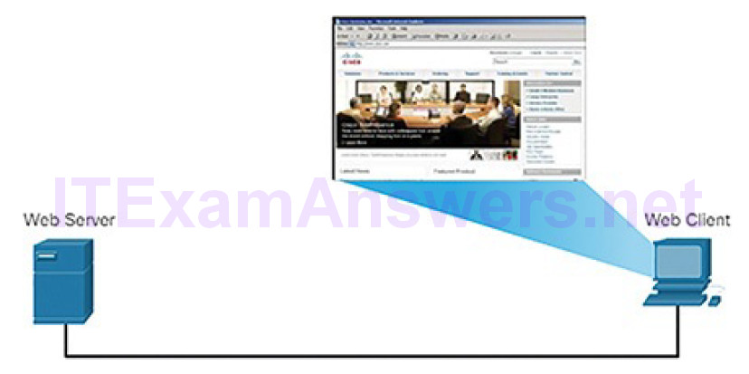
Figure 4-25 Displaying the Web Page
Scenario: Sending and Receiving a Web Page (4.1.2.9)
To summarize network communication processes and protocols, consider the scenario of sending and receiving a web page. Figure 4-26 lists some of the protocols used between a web server and a web client:
- HTTP: This application protocol governs the way a web server and a web client interact.
- TCP: This transport protocol manages individual conversations. TCP divides the HTTP messages into smaller pieces, called segments. TCP is also responsible for controlling the size and rate at which messages are exchanged between the server and the client.
- IP: This Internet protocol is responsible for taking the formatted segments from TCP, encapsulating them into packets, assigning them the appropriate addresses, and delivering them to the destination host.
- Ethernet: This network access protocol is responsible for taking the packets from IP and formatting them to be transmitted over the media.
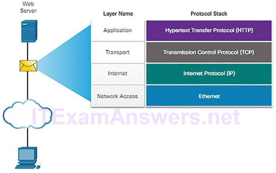
Figure 4-26 Interaction of Protocols
In the previously shown Figures 4-19 through 4-25 the complete communication process is demonstrated using an example of a web server transmitting data to a client and the client receiving the data:
1. The web server prepared the Hypertext Markup Language (HTML) page as data to be sent.
2. The application protocol HTTP header is added to the front of the HTML data. The header contains various information, including the HTTP version that the server is using and a status code indicating it has information for the web client.
3. The HTTP application layer protocol delivers the HTML-formatted web page data to the transport layer. TCP segments the data adding source and destination port numbers.
4. The IP information is added to the front of the TCP information. IP assigns the appropriate source and destination IP addresses. The TCP segment has now been encapsulated in an IP packet.
5. The Ethernet protocol adds information to both ends of the IP packet to create a frame. This frame is delivered through the network towards the web client.
6. The client receives the data link frames that contain the data. Each protocol header is processed and then removed in the opposite order it was added.The Ethernet information is processed and removed, followed by the IP protocol information, the TCP information, and finally the HTTP information.
7. The web page information is then passed on to the client’s web browser software.
Cybersecurity analysts are adept at using tools to view the behavior of network protocols. For example, Wireshark captures all the details of the protocols encapsulated in packets and data that travels through the network. This course will focus on the use of Wireshark and the interpretation of Wireshark data.
Lab 4.1.2.10: Introduction to Wireshark
Wireshark is a software protocol analyzer, or “packet sniffer” application, used for network troubleshooting, analysis, software and protocol development, and education. Wireshark is used throughout the course to demonstrate network concepts. In this lab, you will use Wireshark to capture and analyze network traffic.
Ethernet and Internet Protocol (IP) (4.2)
In this section, you will learn how the Ethernet and IP protocols support network communication.
Ethernet (4.2.1)
In this topic, you will learn how Ethernet supports network communication.
The Ethernet Protocol (4.2.1.1)
Ethernet operates in the data link layer and the physical layer, as shown in Figure 4-27. It is a family of networking technologies that are defined in the IEEE 802.2 and 802.3 standards. Ethernet relies on the two separate sublayers of the data link layer to operate, the Logical Link Control (LLC) and the Media Access Control (MAC) sublayers.
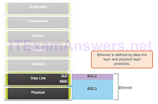
Figure 4-27 Ethernet
LLC is responsible for communication with the network layer. MAC is implemented by the computer’s network interface card (NIC). The MAC sublayer has two primary responsibilities:
- Data encapsulation: Ethernet encapsulates the IP packet into a frame, adding timing information, destination and source MAC addresses, and an error checking feature.
- Media access control: Ethernet manages the process of converting the frame into bits and sending the frame out onto the network. In older wired networks, devices could not send and receive data at the same time. This is still the case for wireless networks. In such situations, Ethernet use a process to determine when a device can send and what to do if the data sent by two devices collides on the network. This process is discussed later in the chapter.
The Ethernet Frame (4.2.1.2)
The minimum Ethernet frame size is 64 bytes and the maximum is 1518 bytes. This includes all bytes from the Destination MAC Address field through the Frame Check Sequence (FCS) field. The Preamble field is not included when describing the size of a frame.
Any frame less than 64 bytes in length is considered a “collision fragment” or“runt frame.” Frames with more than 1518 bytes are considered “jumbo frames” or “baby giant frames.”
If the size of a transmitted frame is less than the minimum or greater than the maximum, the receiving device drops the frame. Dropped frames are likely to be the result of collisions or other unwanted signals and are therefore considered invalid.
Figure 4-28 shows the structure of the Ethernet II frame.

Figure 4-28 Ethernet II Frame Fields
Table 4-3 describes the function of each field in the Ethernet frame.
Table 4-3 Description of the Ethernet Frame Fields
| Frame Field | Description |
|---|---|
| Preamble and Start Frame Delimiter fields | The Preamble field (7 bytes) and Start Frame Delimiter (SFD)—also called Start of Frame—field (1 byte) are used for synchronization between the sending and receiving devices. These first 8 bytes of the frame are used to get the attention of the receiving nodes. Essentially, the first few bytes tell the receivers to get ready to receive a new frame. |
| Destination MAC Address field |
This 6-byte field is the identifier for the intended recipient. As you will recall, this address is used by Layer 2 to assist devices in determining if a frame is addressed to them. The address in the frame is compared to the MAC address in the device. If there is a match, the device accepts the frame. Can be a unicast, multicast, or broadcast address. |
| Source | This 6-byte field identifies the frame’s originating NIC or interface. |
| MAC Address field |
Must be a unicast address. |
| EtherType field | This 2-byte field identifies the upper layer protocol encapsulated in the Ethernet frame. Common values are, in hexadecimal, 0x800 for IPv4, 0x86DD for IPv6, and 0x806 for ARP. |
| Data field | This field (46–1500 bytes) contains the encapsulated data from a higher layer, which is a generic Layer 3 PDU, or more commonly, an IPv4 packet. All frames must be at least 64 bytes long. If a small packet is encapsulated, additional bits called a pad are used to increase the size of the frame to this minimum size. |
| Frame Check Sequence field | The Frame Check Sequence (FCS) field (4 bytes) is used to detect errors in a frame. It uses a cyclic redundancy check (CRC). The sending device includes the results of a CRC in the FCS field of the frame. The receiving device receives the frame and generates a CRC to look for errors. If the calculations match, no error occurred. Calculations that do not match are an indication that the data has changed; therefore, the frame is dropped. A change in the data could be the result of a disruption of the electrical signals that represent the bits. |
MAC Address Format (4.2.1.3)
An Ethernet MAC address is a 48-bit binary value expressed as 12 hexadecimal digits (4 bits per hexadecimal digit). Hexadecimal digits use the numbers 0 to 9 and the letters A to F. Figure 4-29 shows the equivalent decimal and hexadecimal values for binary 0000 to 1111. Hexadecimal is commonly used to represent binary data. IPv6 addresses are another example of hexadecimal addressing.
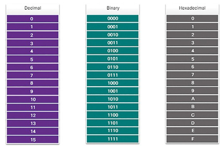
Figure 4-30 Different Representations of MAC Addresses
All data that travels on the network is encapsulated in Ethernet frames. A cybersecurity analyst should be able to interpret the Ethernet data that is captured by protocol analyzers and other tools.
Activity 4.2.1.4: Ethernet Frame Fields
Refer to the online course to complete this Activity.
IPv4 (4.2.2)
In this topic, you will learn how the IPv4 protocol supports network communications.
IPv4 Encapsulation (4.2.2.1)
As we know, Ethernet operates at the data link and physical layers of the OSI model. We will now focus on the network layer. Just as the data link layer encapsulates IP packets as frames, the network layer encapsulates segments from the transport layer into IP packets, as shown in Figure 4-31.
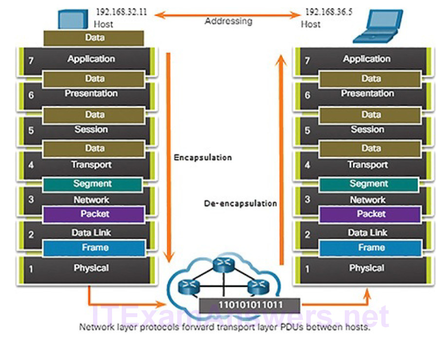
Figure 4-31 The Exchange of Data
IP encapsulates the transport layer segment by adding an IP header. This headerincludes information that is necessary to deliver the packet to the destination host.
Figure 4-32 illustrates how the transport layer PDU is then encapsulated by the network layer PDU to create an IP packet.
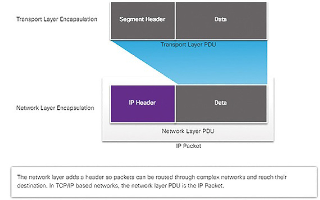
Figure 4-32 Network Layer PDU = IP Packet
IPv4 Characteristics (4.2.2.2)
The basic characteristics of IP, as shown in Figure 4-33, are
- Connectionless: No connection with the destination is established before sending data packets.
- Best effort: IP is inherently unreliable because packet delivery is not guaranteed.
- Media independent: Operation is independent of the medium (i.e., copper, fiber optic, or wireless) carrying the data.
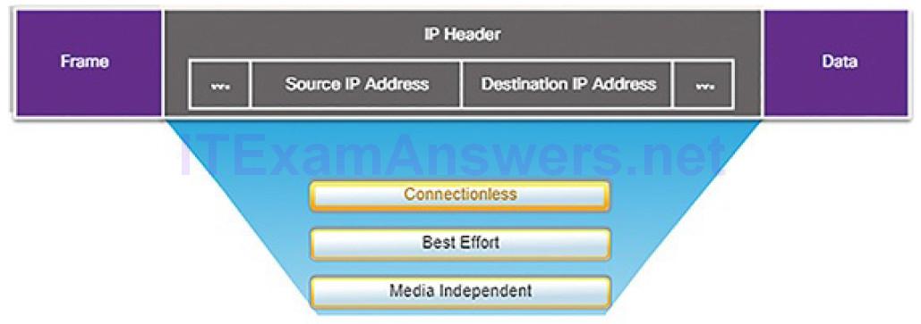
Figure 4-33 Characteristics of the IP Protocol
Connectionless
IP is connectionless, meaning that no dedicated end-to-end connection is created before data is sent. As shown in Figure 4-34, connectionless communication is conceptually similar to sending a letter to someone without notifying the recipient in advance.
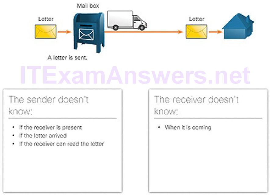
Figure 4-34 Connectionless Communication: Mail Analogy
Connectionless data communications work on the same principle. As shown in Figure 4-35, IP requires no initial exchange of control information to establish an end-to-end connection before packets are forwarded.
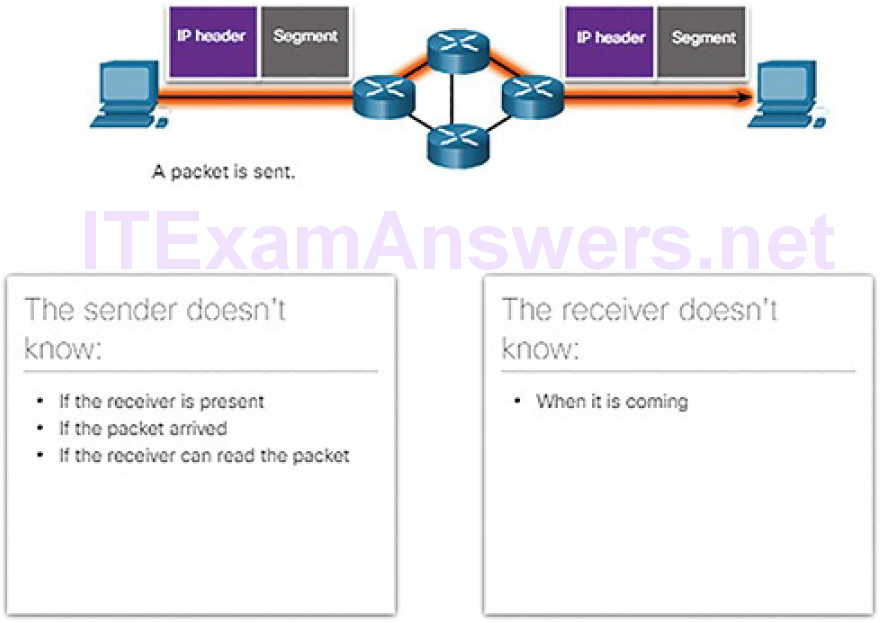
Figure 4-35 Connectionless Communication over Networks
IP also does not require additional fields in the header to maintain an established connection. This process greatly reduces the overhead of IP. However, with no pre-established end-to-end connection, senders are unaware whether destination devices are present and functional when sending packets, nor are they aware if the destination receives the packet, or if they are able to access and read the packet.
Best Effort
Figure 4-36 illustrates the unreliable, or best-effort, delivery characteristic of the IP protocol. The IP protocol does not guarantee that all packets that are delivered are, in fact, received.
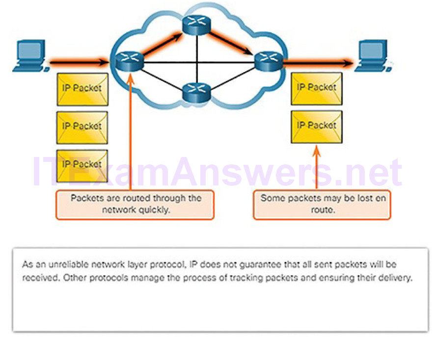
Figure 4-36 Best Effort Process
Unreliable means that IP does not have the capability to manage and recover from undelivered or corrupt packets. This is because while IP packets are sent with information about the location of delivery, they contain no information that can be processed to inform the sender whether delivery was successful. Packets may arrive at the destination corrupted, out of sequence, or not at all. IP provides no capability for packet retransmissions if errors occur.
If out-of-order packets are delivered, or packets are missing, then upper layer services must resolve these issues. This allows IP to function very efficiently. In the TCP/IP protocol suite, reliability is the role of the transport layer, as we will discuss later in the chapter.
Media Independent
IP operates independently of the media that carry the data at lower layers of the protocol stack. As shown in Figure 4-37, IP packets can be sent as electronic signals over copper cable, as optical signals over fiber, or wirelessly as radio signals.
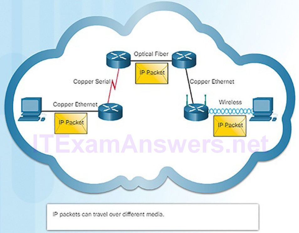
Figure 4-37 Media Independent Process
It is the responsibility of the data link layer to take an IP packet and prepare it for transmission over the communications medium. This means that the transport of IP packets is not limited to any particular medium.
There is, however, one major characteristic of the media that the network layer considers: the maximum size of the PDU that each medium can transport. This characteristic is referred to as the maximum transmission unit (MTU). Part of the control communication between the data link layer and the network layer is the establishment of a maximum size for the packet. The data link layer passes the MTU value up to the network layer. The network layer then determines how large packets can be.
In some cases, an intermediate device, usually a router, must split up a packet when forwarding it from one medium to another medium with a smaller MTU. This process is called fragmenting the packet, or fragmentation.
Activity 4.2.2.3: IPv4 Characteristics
Refer to the online course to complete this Activity.
The IPv4 Packet (4.2.2.4)
An IPv4 packet header consists of fields containing important information about the packet. These fields contain binary numbers which are examined by the Layer 3 process. The binary values of each field identify various settings of the IP packet. Protocol header diagrams, which are read left to right, and top down, provide a visual to refer to when discussing protocol fields. The IP protocol header diagram in Figure 4-38 identifies the fields of an IPv4 packet.
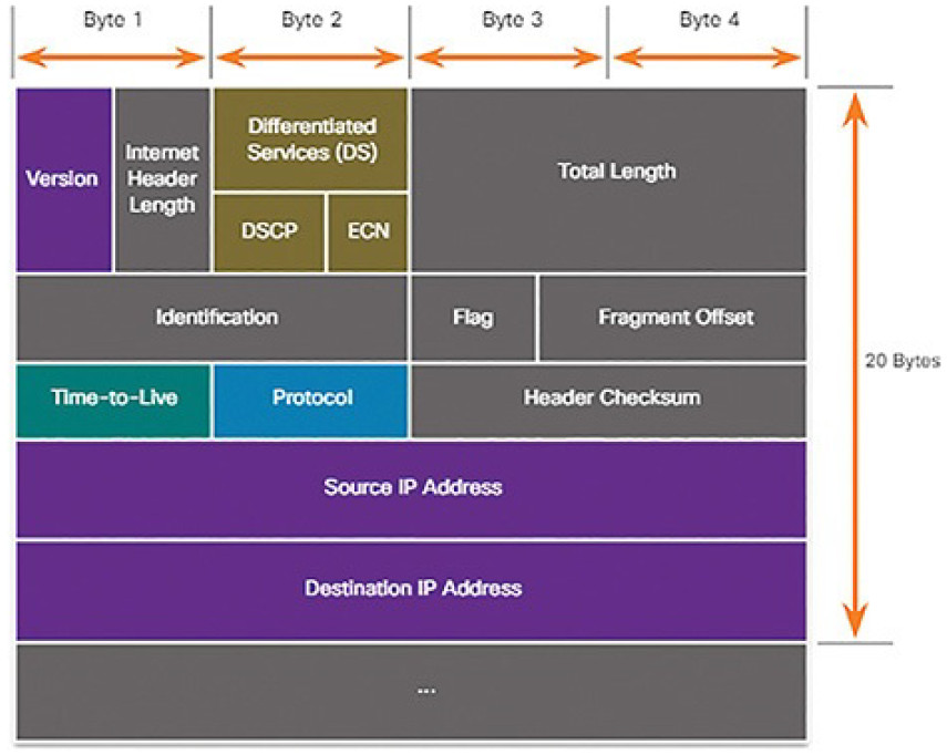
Figure 4-38 IPv4 Packet Headers
The fields in the IPv4 packet header are discussed in more detail later in the course.
The two most commonly referenced fields are the source and destination IPaddresses. These fields identify where the packet is coming from and where it is going.
Cybersecurity analysts must have a firm grasp of the operation of IP and the meaning of IP data that is captured by protocol analyzers and other network devices. This data is mostly in the form of the information contained in IP packet headers.
Video Demonstration 4.2.2.5: Sample IPv4 Headers in Wireshark
Refer to the online course to view this video.
IPv4 Addressing Basics (4.2.3)
In this topic, you will learn how IP addresses enable network communication.
IPv4 Address Notation (4.2.3.1)
An IPv4 address is simply a series of 32 binary bits (ones and zeros). It is very difficult for humans to read a binary IPv4 address. For this reason, the 32 bits are grouped into four 8-bit bytes called octets. Each octet is represented as its decimal value, separated by a decimal point or period. This is referred to as dotted-decimal notation.
When a host is configured with an IPv4 address, it is entered as a dotted-decimal number such as 192.168.10.10. The equivalent address in binary is 1100000.10101000.00001010.00001010. The conversion to dotted-decimal is shown in Figure 4-39.
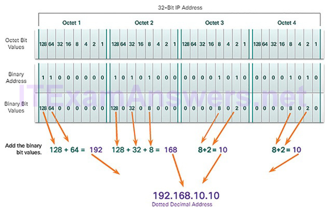
Figure 4-39 Converting Binary to Dotted-Decimal
Note
If you are new to binary-to-decimal conversion, search the Internet for tutorials.
Some proficiency in binary will be helpful in your job as a cybersecurity analyst.
IPv4 Host Address Structure (4.2.3.2)
An IPv4 address is a hierarchical address that is made up of a network portion and a host portion. When determining the network portion versus the host portion, it is necessary to look at the 32-bit stream. Within the 32-bit stream, a portion of the bits identifies the network, and a portion of the bits identifies the host, as shown in Figure 4-40.

Figure 4-40 IPv4 Address Structure
The bits within the network portion of the address must be identical for all devices that reside in the same network. The bits within the host portion of the address must be unique to identify a specific host within a network. For example, if you look at the IPv4 addresses for various devices in your home network, you will most likely see the same network portion. Example 4-1 shows the IPv4 configuration for a Windows computer.
Example 4-1 Checking IP Configuration on a Windows PC
C:\> ipconfig

Windows IP Configuration

Ethernet adapter Ethernet:
Connection-specific DNS Suffix . :
Link-local IPv6 Address . . . . . : fe80::1074:d6c8:f89d:43ad%18
IPv4 Address. . . . . . . . . . . : 192.168.10.10
Subnet Mask . . . . . . . . . . . : 255.255.255.0
Default Gateway . . . . . . . . . : 192.168.10.1

<output omitted>

C:\>
Figure 4-41 shows the IPv4 address for an iPhone.
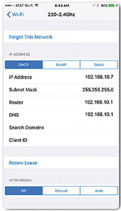
Figure 4-41 iPhone IPv4 Address
Figure 4-42 shows the IPv4 configuration for an Xbox One gaming console. Notice that all three devices share the same network address portion, 192.168.10, and that each device has a unique host portion, .10, .7, and .12, respectively.
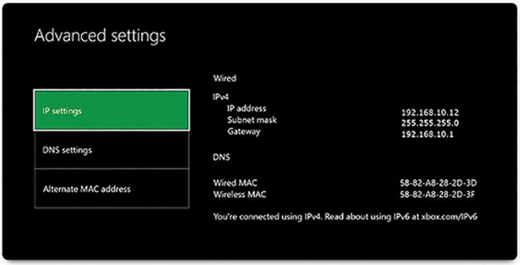
Figure 4-42 Xbox One IPv4 Address
But how do hosts know which portion of the 32 bits identifies the network and which portion identifies the host? That is the job of the subnet mask.
IPv4 Subnet Mask and Network Address (4.2.3.3)
The subnet mask is logically ANDed with the host address to determine the network address. Logical AND is the comparison of 2 bits that produce the results shown in Figure 4-43. Note how only a 1 AND 1 produces a 1.

Figure 4-43 Logical AND Operation
To identify the network address of an IPv4 host, the IPv4 address is logically ANDed, bit by bit, with the subnet mask. ANDing between the address and the subnet mask yields the network address.
To illustrate how AND is used to discover a network address, consider a host with the IPv4 address 192.168.10.10 and a subnet mask of 255.255.255.0. Figure 4-44 displays the host IPv4 address and converted binary address.

Figure 4-44 Host IP Binary Address
The host subnet mask binary address is added in Figure 4-45.

Figure 4-45 Binary Address of 255.255.255.0
The yellow highlighted sections in Figure 4-46 identify the AND bits that produced a binary 1 in the AND Results row. All other bit comparisons produced binary 0s. Notice how the last octet no longer has any binary 1 bits.
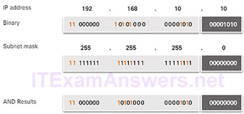
Figure 4-46 AND Operation
Finally, Figure 4-47 displays the resulting network address 192.168.10.0 255.255.255.0. Therefore, host 192.168.10.10 is on network 192.168.10.0 255.255.255.0.
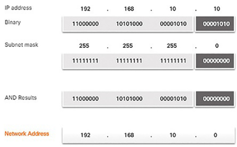
Figure 4-47 Resulting Network Address
Subnetting Broadcast Domains (4.2.3.4)
The 192.168.10.0/24 network can support 254 hosts. Larger networks, such as 172.16.0.0/16, can support many more host addresses (over 65,000). However, this can potentially create a larger broadcast domain. A problem with a large broadcast domain is that these hosts can generate excessive broadcasts and negatively affect the network. In Figure 4-48, LAN 1 connects 400 users that could each generate broadcast traffic. That much broadcast traffic can slow down network operations. It can also slow device operations because each device must accept and process each broadcast packet.
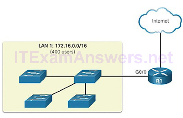
Figure 4-48 A Large Broadcast Domain
The solution is to reduce the size of the network to create smaller broadcast domains in a process called subnetting. These smaller network spaces are called subnets.
In Figure 4-49, for example, the 400 users in LAN 1 with network address 172.16.0.0/16 have been divided into two subnets of 200 users each: 172.16.0.0/24 and 172.16.1.0/24. Broadcasts are only propagated within the smaller broadcast domains. Therefore, a broadcast in LAN 1 would not propagate to LAN 2.
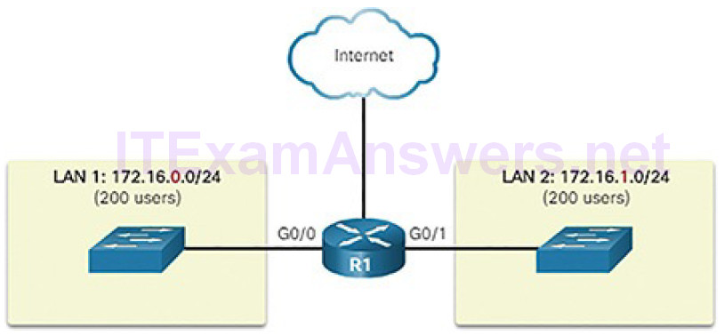
Figure 4-49 Communicating Between Networks
Notice how the prefix length has changed from a /16 to a /24. This is the basis of subnetting: using host bits to create additional subnets.
Note
The terms subnet and network are often used interchangeably. Most networks are a subnet of some larger address block.
Subnetting reduces overall network traffic and improves network performance. It also enables an administrator to implement security policies such as which subnets are allowed or not allowed to communicate together.
There are various ways of using subnets to help manage network devices.
Network administrators can group devices and services into subnets that may be determined by a variety of factors:
Location, such as floors in a building (Figure 4-50)
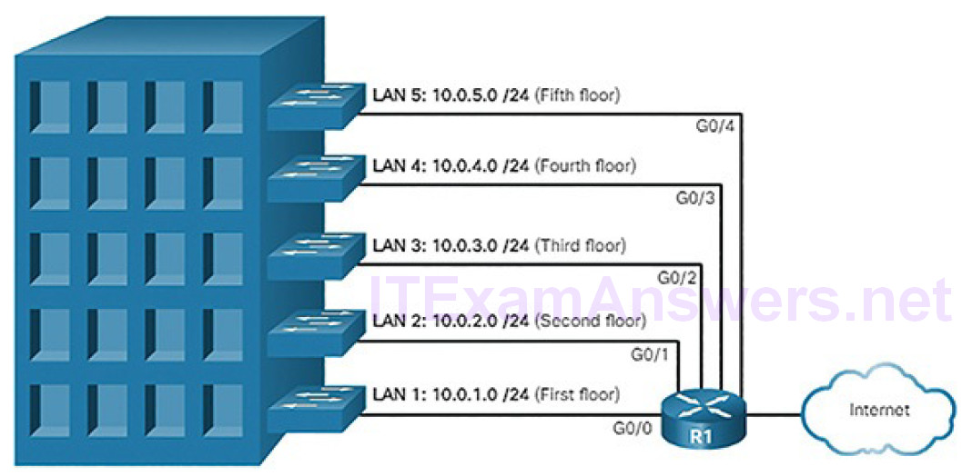
Figure 4-50 Subnetting by Location
Organizational unit (Figure 4-51)
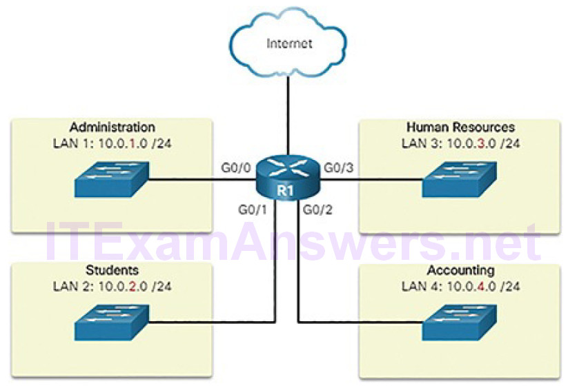
Figure 4-51 Communicating Between Networks
Device type (Figure 4-52)
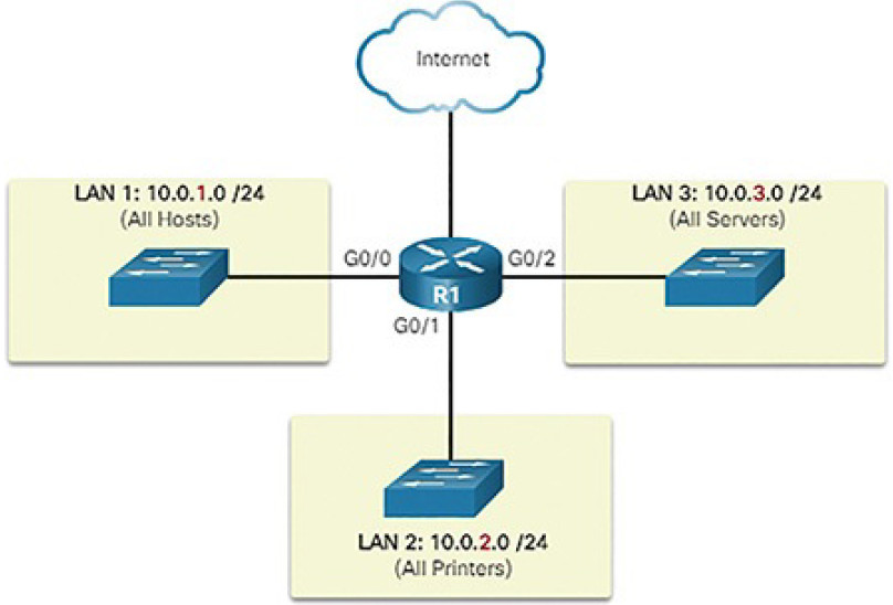
Figure 4-52 Subnetting by Device Type
Any other division that makes sense for the network
A cybersecurity analyst does not need to know how to subnet. However, it is important to know the meaning of the subnet mask and that hosts with addresses on different subnets come from different places in a network.
Video Demonstration 4.2.3.5: Network, Host, and Broadcast Addresses
Refer to the online course to view this video.
Types of IPv4 Addresses (4.2.4)
In this topic, you will learn the type of IPv4 addresses that enable network communication.
IPv4 Address Classes and Default Subnet Masks (4.2.4.1)
There are various types and classes of IPv4 addresses. While address classes are becoming less important in networking, they are still used and referred to commonly in network documentation.
Address Classes
In 1981, IPv4 addresses were assigned using classful addressing as defined in RFC 790. Customers were allocated a network address based on one of three classes, A, B, or C. The RFC divided the unicast ranges into specific classes:
- Class A (0.0.0.0/8 to 127.0.0.0/8): Designed to support extremely large networks with more than 16 million host addresses. It used a fixed /8 prefix with the first octet to indicate the network address and the remaining three octets for host addresses.
- Class B (128.0.0.0/16 to 191.255.0.0/16): Designed to support the needs of moderate to large size networks with up to approximately 65,000 host addresses. It used a fixed /16 prefix with the two high-order octets to indicate the network address and the remaining two octets for host addresses.
- Class C (192.0.0.0/24 to 223.255.255.0/24): Designed to support small networks with a maximum of 254 hosts. It used a fixed /24 prefix with the first three octets to indicate the network and the remaining octet for the host addresses.
Note
There is also a Class D multicast block consisting of 224.0.0.0 to 239.0.0.0 and a Class E experimental address block consisting of 240.0.0.0 to 255.0.0.0.
As shown in Figure 4-53, the classful system allocated 50% of the available IPv4 addresses to 128 Class A networks, 25% of the addresses to Class B, and then Class C shared the remaining 25% with Classes D and E. Although appropriate at the time, as the Internet grew it was obvious that this method was wasting addresses and depleting the number of available IPv4 network addresses.
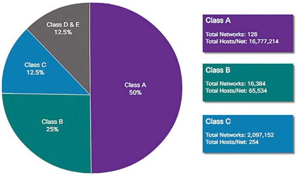
Figure 4-53 Summary of Classful Addressing
Classful addressing was abandoned in the late 1990s for the newer and current classless addressing system. However, as we will see later in this section, classless addressing was only a temporary solution to the depletion of IPv4 addresses.
Reserved Private Addresses (4.2.4.2)
Public IPv4 addresses are addresses which are globally routed between ISP routers. However, not all available IPv4 addresses can be used on the Internet. There are blocks of addresses called private addresses that are used by most organizations to assign IPv4 addresses to internal hosts.
In the mid-1990s, private IPv4 addresses were introduced because of the depletion of IPv4 address space. Private IPv4 addresses are not unique and can be used by any internal network.
These are the private address blocks:
- 10.0.0.0/8 or 10.0.0.0 to 10.255.255.255
- 172.16.0.0/12 or 172.16.0.0 to 172.31.255.255
- 192.168.0.0/16 or 192.168.0.0 to 192.168.255.255
It is important to know that addresses within these address blocks are not allowed on the Internet and must be filtered (discarded) by Internet routers. For example, as shown in Figure 4-54, users in networks 1, 2, and 3 are sending packets to remote destinations. The ISP routers would see that the source IPv4 addresses in the packets are from private addresses and would, therefore, discard the packets.
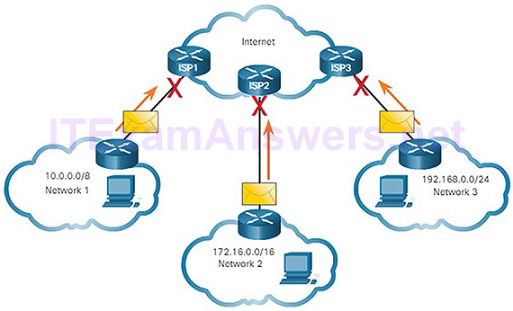
Figure 4-54 Private Addresses Cannot Be Routed Over the Internet
Most organizations use private IPv4 addresses for their internal hosts. However, these RFC 1918 addresses are not routable on the Internet and must be translated to a public IPv4 addresses. Network Address Translation (NAT) is used to translate between private IPv4 and public IPv4 addresses. This is usually done on the router that connects the internal network to the ISP’s network.
Home routers provide the same capability. For instance, most home routers assign IPv4 addresses to their wired and wireless hosts from the private address of 192.168.1.0/24. The home router interface that connects to the Internet service provider (ISP) network is often assigned a public IPv4 address to use on the Internet.
The Default Gateway (4.2.5)
In this topic, you will learn how the default gateway enables network communication.
Host Forwarding Decision (4.2.5.1)
A host can send a packet to three types of destinations, as shown in Figure 4-55:
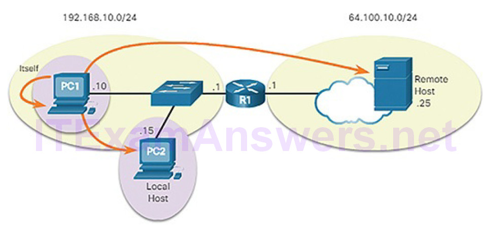
Figure 4-55 Three Types of Destinations
Itself: A host can ping itself by sending a packet to a special IPv4 address of 127.0.0.1, which is referred to as the loopback interface. Pinging the loopback interface tests the TCP/IP protocol stack on the host.
Local host: This is a host on the same local network as the sending host (from PC1 to PC2). The hosts share the same network address.
Remote host: This is a host on a remote network. The hosts do not share the same network address. Notice that R1, a router, is in between PC1 and the remote host. R1 is the default gateway for PC1 and PC2. R1’s job is to route any traffic destined for remote networks.
As we have seen, the subnet mask is used to determine to which network an IPv4 host address belongs. Whether a packet is destined for a local host or a remote host is determined by the IP address and subnet mask combination of the source device compared to the IP address and subnet mask combination of the destination device. PC 1 knows it is on the 192.168.10.0/24 network. Therefore,it knows that PC 2 is also on the same network and that the server, Remote Host, is not on the same network. When a source device sends a packet to a remote host, then the help of routers and routing is needed. Routing is the process of identifying the best path to a destination. The router connected to the local network segment is referred to as the default gateway.
Default Gateway (4.2.5.2)
As shown Figure 4-56, three dotted-decimal IPv4 addresses must be configured when assigning an IPv4 configuration to host:
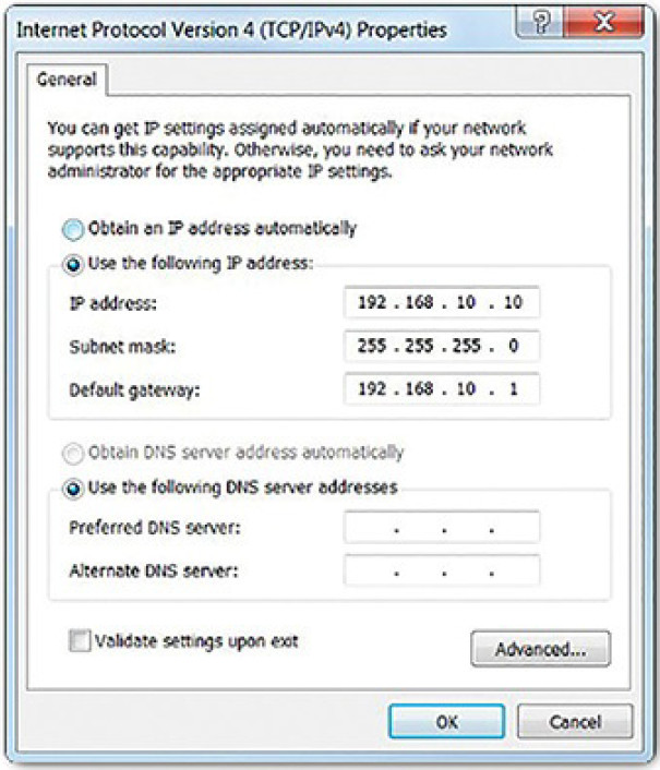
Figure 4-56 Checking Windows IPv4 Properties
IPv4 address: Unique IPv4 address of the host
Subnet mask: Used to identify the network/host portion of the IPv4 address
Default gateway: Identifies the local gateway (i.e., local router interface IPv4 address) to reach remote networks
The default gateway is the network device that can route traffic to other networks. It is the router that can route traffic out of the local network.
If you use the analogy that a network is like a room, then the default gateway is like a doorway. If you want to get to another room or network, you need to find the doorway.
Alternatively, a PC or computer that does not know the IP address of the default gateway is like a person, in a room, that does not know where the doorway is. They can talk to other people in the room or network, but if they do not know the default gateway address, or there is no default gateway, then there is no way out.
Using the Default Gateway (4.2.5.3)
A host’s routing table will typically include a default gateway. The host receives the IPv4 address of the default gateway either dynamically from Dynamic Host Configuration Protocol (DHCP) or configured manually. In Figure 4-57, PC1 and PC2 are configured with the default gateway’s IPv4 address of 192.168.10.1. Having a default gateway configured creates a default route in the routing table of the PC. A default route is the route or pathway your computer will take when it tries to contact a remote network.
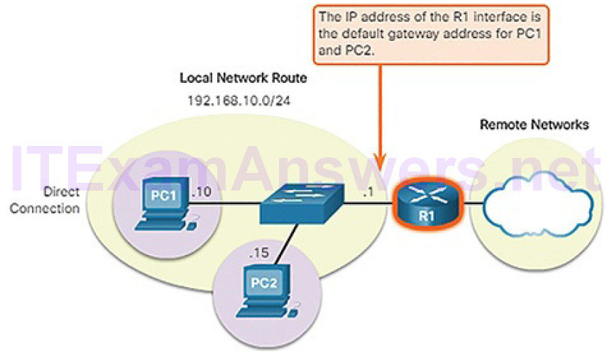
Figure 4-57 Host Default Gateway
The default route is derived from the default gateway configuration and is placedin the host computer’s routing table. Both PC1 and PC2 will have a default route for sending all traffic destined to remote networks to R1, as shown in Figure 4-58.

Figure 4-58 Local Topology for PC1
ou can view the routing table for a Windows host using either the netstat -r or route print command, as shown in Example 4-2.
Example 4-2 IPv4 Routing Table for PC1
C:\Users\PC1> netstat -r
<output omitted>
IPv4 Route Table
==============================================================================
Active Routes:
Network Destination Netmask Gateway Interface Metric
0.0.0.0 0.0.0.0 192.168.10.1 192.168.10.10 25
127.0.0.0 255.0.0.0 On-link 127.0.0.1 306
127.0.0.1 255.255.255.255 On-link 127.0.0.1 306
127.255.255.255 255.255.255.255 On-link 127.0.0.1 306
192.168.10.0 255.255.255.0 On-link 192.168.10.10 281
192.168.10.10 255.255.255.255 On-link 192.168.10.10 281
192.168.10.255 255.255.255.255 On-link 192.168.10.10 281
224.0.0.0 240.0.0.0 On-link 127.0.0.1 306
224.0.0.0 240.0.0.0 On-link 192.168.10.1 281
255.255.255.255 255.255.255.255 On-link 127.0.0.1 306
255.255.255.255 255.255.255.255 On-link 192.168.10.1 281
==============================================================================
<output omitted>
C:\Users\PC1>
IPv6 (4.2.6)
In this topic, you will learn how the IPv6 protocol supports network communications.
Need for IPv6 (4.2.6.1)
The depletion of IPv4 address space has been the motivating factor for moving to IPv6. As Africa, Asia, and other areas of the world become more connected to the Internet, there are not enough IPv4 addresses to accommodate this growth. As shown in Figure 4-59, four out of the five Regional Internet Registries (RIRs) have run out of IPv4 addresses.
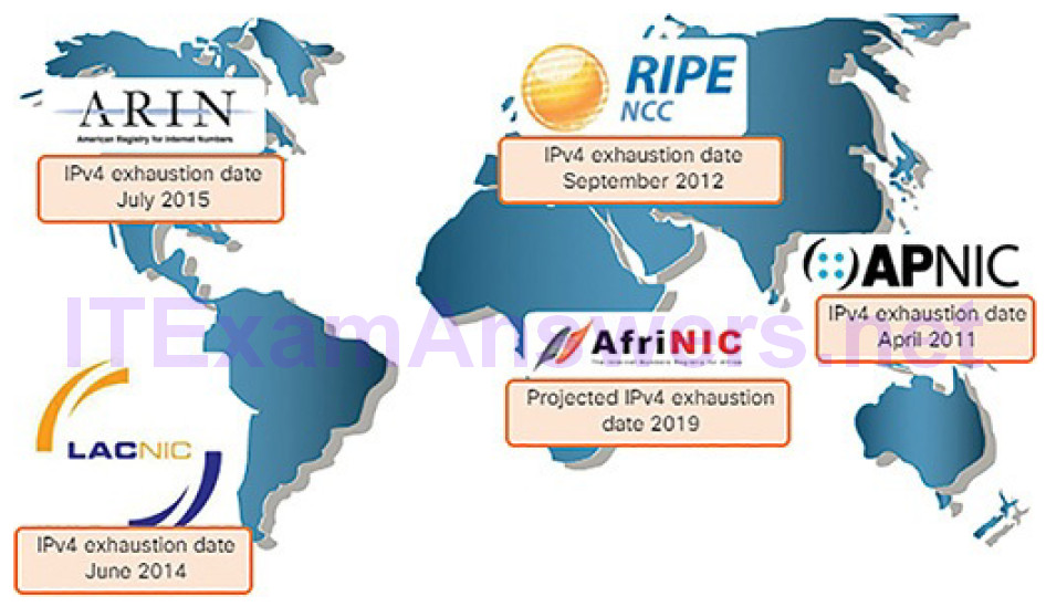
Figure 4-59 RIR IPv4 Exhaustion Dates
IPv4 has a theoretical maximum of 4.3 billion addresses. Private addresses in combination with Network Address Translation (NAT) have been instrumental in slowing the depletion of IPv4 address space. However, NAT breaks many applications and has limitations that severely impede peer-to-peer communications.
Note
NAT is discussed in more detail later in the chapter.
IPv6 Size and Representation (4.2.6.2)
IPv6 is designed to be the successor to IPv4. IPv6 has a 128-bit address space, providing for 340 undecillion addresses. (That is the number 340, followed by 36 zeros.) However, IPv6 is more than just a bigger pool of addresses. When the Internet Engineering Task Force (IETF) began its development of a successor to IPv4, it used this opportunity to fix the limitations of IPv4 and include additional enhancements. One example is Internet Control Message Protocol version 6 (ICMPv6), which includes address resolution and address auto-configuration not found in ICMP for IPv4 (ICMPv4).
IPv6 addresses are written as a string of hexadecimal values. Every 4 bits is represented by a single hexadecimal digit, for a total of 32 hexadecimal values. IPv6 addresses are not case-sensitive and can be written in either lowercase or uppercase.
As shown in Figure 4-60, the format for writing an IPv6 address is x:x:x:x:x:x:x:x, with each “x” consisting of four hexadecimal values.
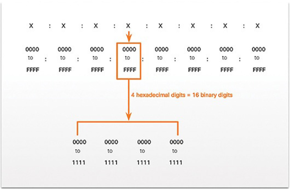
Figure 4-60 Hextets When referring
When referring to 8 bits of an IPv4 address, we use the term octet. In IPv6, a hextet is the unofficial term used to refer to a segment of 16 bits or fourhexadecimal values. Each “x” is a single hextet, 16 bits or four hexadecimal digits.
IPv6 Address Formatting (4.2.6.3)
It is no problem for computers to read the new 128-bit IPv6 addressing. IPv6 just adds more ones and zeros to the source and destination addresses in the packet. For humans, though, the change from a 32-bit address written in dotted-decimal notation to an IPv6 address written as a series of 32 hexadecimal digits can be quite an adjustment. Techniques have been developed to compress the written IPv6 address into a more manageable format.
Compressing IPv6 Addresses
IPv6 addresses are written as a string of hexadecimal values. Every 4 bits is represented by a single hexadecimal digit for a total of 32 hexadecimal values. Table 4-4 shows a fully expanded IPv6 address and two methods of making it more easily readable.
Table 4-4 Compressing an IPv6 Address
| Description | IPv6 Address |
|---|---|
| Fully expanded | 2001:0DB8:0000:1111:0000:0000:0000:0200 |
| No leading 0s | 2001:DB8:0:1111:0:0:0:200 |
| Compressed | 2001:DB8:0:1111::200 |
There are two rules that help reduce the number of digits needed to represent an IPv6 address.
Rule 1: Omit Leading Zeros
The first rule to help reduce the notation of IPv6 addresses is to omit any leading 0s (zeros) in any 16-bit section. For example:
- 0DB8 can be represented as DB8.
- 0000 can be represented as 0.
- 0200 can be represented as 200.
Rule 2: Omit One “all zeros” Segment
The second rule to help reduce the notation of IPv6 addresses is that a double colon (::) can replace any group of consecutive segments that contain only zeros. The double colon (::) can only be used once within an address, otherwise there would be more than one possible resulting address.
IPv6 Prefix Length (4.2.6.4)
Recall that the prefix, or network portion, of an IPv4 address can be identified by a dotted-decimal subnet mask or prefix length (slash notation). For example, an IPv4 address of 192.168.1.10 with dotted-decimal subnet mask 255.255.255.0 is equivalent to 192.168.1.10/24.
IPv6 uses the prefix length to represent the prefix portion of the address. IPv6 does not use the dotted-decimal subnet mask notation. The prefix length is used to indicate the network portion of an IPv6 address using the IPv6 address/prefix length.
The prefix length can range from 0 to 128. A typical IPv6 prefix length for LANs and most other types of networks is /64, as shown in Figure 4-61. This means the prefix or network portion of the address is 64 bits in length, leaving another 64 bits for the interface ID (host portion) of the address.
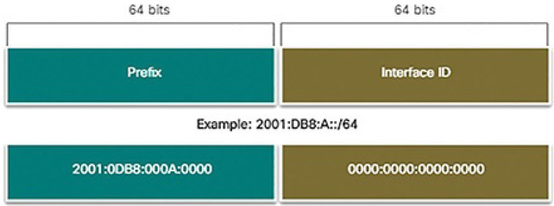
Figure 4-61 IPv6 Prefix Length
Activity 4.2.6.5: IPv6 Address Notation
Refer to the online course to complete this Activity.
Video Tutorial 4.2.6.6: Layer 2 and Layer 3 Addressing
Refer to the online course to view this video.
Connectivity Verification (4.3)
In this section, you will learn how to use common testing utilities to verify and test network connectivity.
ICMP (4.3.1)
In this topic, you will learn how ICMP is used to test network connectivity.
ICMPv4 Messages (4.3.1.1)
Although IP is only a best-effort protocol, the TCP/IP suite does provide for messages to be sent in the event of certain errors. These messages are sent using the services of ICMP. The purpose of these messages is to provide feedback about issues related to the processing of IP packets under certain conditions, not to make IP reliable. ICMP messages are not required and are often not allowed within a network for security reasons.
ICMP is available for both IPv4 and IPv6. ICMPv4 is the messaging protocol for IPv4. ICMPv6 provides these same services for IPv6 but includes additional functionality. In this course, the term ICMP will be used when referring to both ICMPv4 and ICMPv6.
The types of ICMP messages and the reasons why they are sent, are extensive. We will discuss some of the more common messages.
ICMP messages common to both ICMPv4 and ICMPv6 include:
- Host confirmation
- Destination or Service Unreachable
- Time Exceeded
- Route Redirection
Host Confirmation
An ICMP Echo message can be used to determine if a host is operational. The local host sends an ICMP Echo Request to a host. If the host is available, the destination host responds with an Echo Reply. These ICMP Echo messages are the basis of the ping utility. Figure 4-62 shows an Echo Request message being sent from H1 to H2.
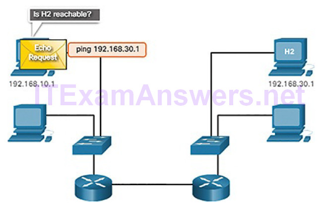
Figure 4-62 Ping to a Remote Host
Figure 4-63 shows an Echo Reply message being sent from H2 back to H1 confirming that H2 is on the network.
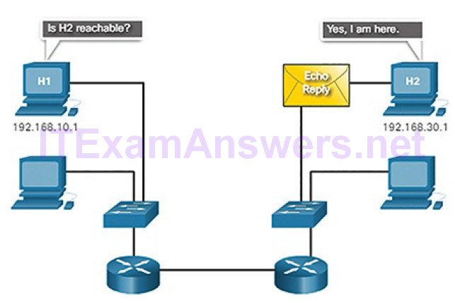
Figure 4-63 Reply from Remote Host
Destination or Service Unreachable
When a host or gateway receives a packet that it cannot deliver, it can use an ICMP Destination Unreachable message to notify the source that the destination or service is unreachable. The message will include a code that indicates why the packet could not be delivered.
These are some of the Destination Unreachable codes for ICMPv4:
0: Net unreachable
1: Host unreachable
2: Protocol unreachable
3: Port unreachable
Note
ICMPv6 has similar but slightly different codes for Destination Unreachable messages.
Time Exceeded
An ICMPv4 Time Exceeded message is used by a router to indicate that a packet cannot be forwarded because the Time to Live (TTL) field of the packet was decremented to 0. If a router receives a packet and decrements the TTL field inthe IPv4 packet to zero, it discards the packet and sends a Time Exceeded message to the source host.
ICMPv6 also sends a Time Exceeded message if the router cannot forward an IPv6 packet because the packet has expired. IPv6 does not have a TTL field; it uses the Hop Limit field to determine if the packet has expired.
ICMPv6 RS and RA Messages (4.3.1.2)
The informational and error messages found in ICMPv6 are very similar to the control and error messages implemented by ICMPv4. However, ICMPv6 has new features and improved functionality not found in ICMPv4. ICMPv6 messages are encapsulated in IPv6.
ICMPv6 includes four new protocols as part of the Neighbor Discovery Protocol (ND or NDP).
Messaging between an IPv6 router and an IPv6 device:
- Router Solicitation (RS) message
- Router Advertisement (RA) message
Messaging between IPv6 devices:
- Neighbor Solicitation (NS) message
- Neighbor Advertisement (NA) message
Note
ICMPv6 ND also includes the Redirect message, which has a similar function to the Redirect message used in ICMPv4.
Figure 4-64 shows an example of a PC and router exchanging Solicitation and Router Advertisement messages.
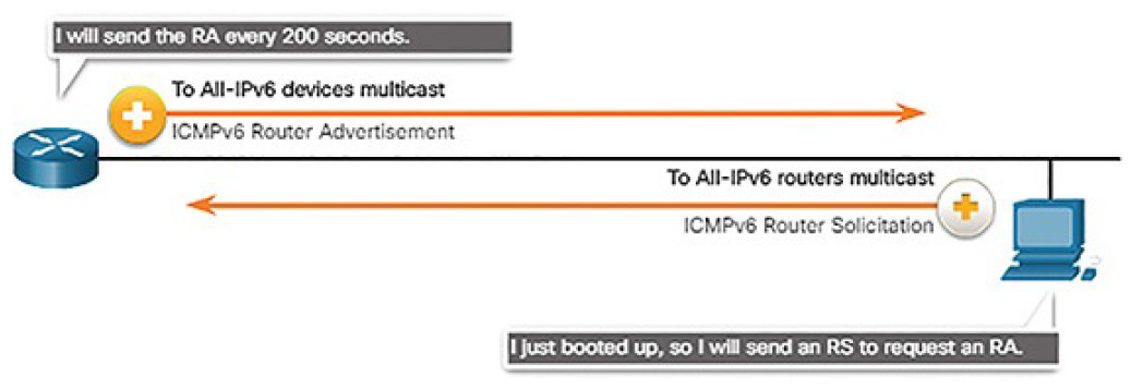
Figure 4-64 IPv6 RS and RA Messages
The host in Figure 4-64 is configured to obtain its addressing information automatically using Stateless Address Autoconfiguration (SLAAC). So the host sends an RS message to the router requesting an RA message.
RA messages are sent by routers to provide addressing information to hosts using SLAAC. The RA message can include addressing information for the host such as the prefix, prefix length, DNS address, and domain name. The router in Figure 4-64 sends an RA message periodically or in response to an RS message. A host using SLAAC will set its default gateway to the link-local address of the router that sent the RA.
Neighbor Solicitation and Neighbor Advertisement messages are used for address resolution and Duplicate Address Detection (DAD).
Address Resolution
Address resolution is used when a device on the LAN knows the IPv6 unicast address of a destination but does not know its Ethernet MAC address. To determine the MAC address for the destination, the device will send an NS message to the solicited node address. The message will include the known (targeted) IPv6 address. The device that has the targeted IPv6 address will respond with an NA message containing its Ethernet MAC address. Figure 4-65 shows two PCs exchanging NS and NA messages.
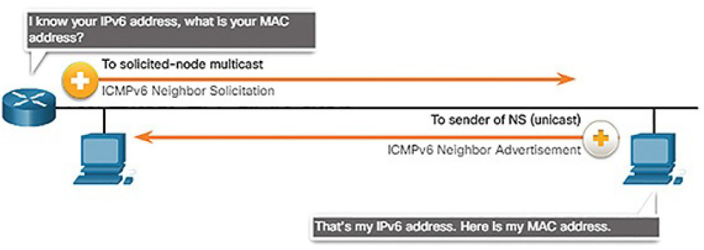
Figure 4-65 IPv6 NS and NA Messages
Duplicate Address Detection
When a device is assigned a global unicast or link-local unicast address, it is recommended that DAD is performed on the address to ensure that it is unique. To check the uniqueness of an address, the device will send an NS message with its own IPv6 address as the targeted IPv6 address, shown in Figure 4-66.
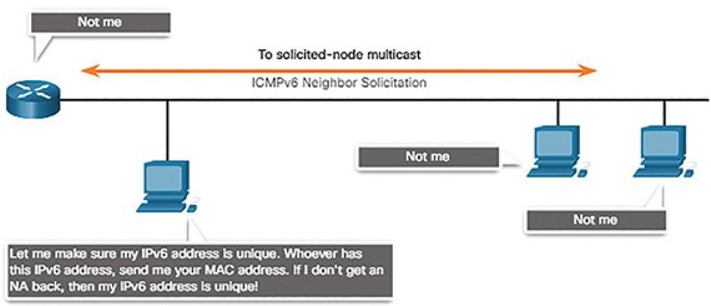
Figure 4-66 IPv6 Duplicate Address Detection
If another device on the network has this address, it will respond with an NA message. This NA message will notify the sending device that the address is in use. If a corresponding NA message is not returned within a certain period of time, the unicast address is unique and acceptable for use.
Note
DAD is not required, but RFC 4861 recommends that DAD is performed on unicast addresses.
Ping and Traceroute Utilities (4.3.2)
In this topic, you will learn how to use ping and traceroute utilities to test network connectivity.
Ping: Testing the Local Stack (4.3.2.1)
Ping is a testing utility that uses ICMP echo request and echo reply messages to test connectivity between hosts. Ping works with both IPv4 and IPv6 hosts.
To test connectivity to another host on a network, an echo request is sent to the host address using the ping command. If the host at the specified address receives the echo request, it responds with an echo reply. As each echo reply is received, ping provides feedback on the time between when the request was sent and when the reply was received. This can be a measure of network performance.
Ping has a timeout value for the reply. If a reply is not received within the timeout, ping provides a message indicating that a response was not received. This usually indicates that there is a problem, but could also indicate that security features blocking ping messages have been enabled on the network.
After all the requests are sent, the ping utility provides a summary that includes the success rate and average round-trip time to the destination.
Pinging the Local Loopback
There are some special testing and verification cases for which we can use ping. One case is for testing the internal configuration of IPv4 or IPv6 on the local host. To perform this test, we ping the local loopback address of 127.0.0.1 for IPv4 (::1 for IPv6). Testing the IPv4 loopback is shown in Figure 4-67.
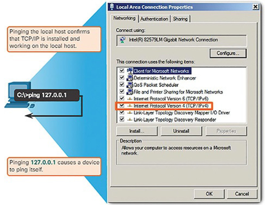
Figure 4-67 Testing the Local TCP/IP Stack
A response from 127.0.0.1 for IPv4, or ::1 for IPv6, indicates that IP is properly installed on the host. This response comes from the network layer. This response is not, however, an indication that the addresses, masks, or gateways are properly configured. Nor does it indicate anything about the status of the lower layer of the network stack. This simply tests IP down through the network layer of IP. An error message indicates that TCP/IP is not operational on the host.
Ping: Testing Connectivity to the Local LAN (4.3.2.2)
You can also use ping to test the ability of a host to communicate on the local network, as shown in Figure 4-68. This is generally done by pinging the IP address of the gateway of the host. A ping to the gateway indicates that the host and the router interface serving as the gateway are both operational on the local network.
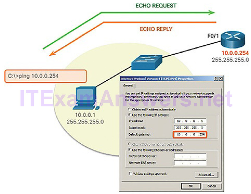
Figure 4-68 Testing IPv4 Connectivity to the Local Network
For this test, the gateway address is most often used because the router is normally always operational. If the gateway address does not respond, a ping can be sent to the IP address of another host on the local network that is known to be operational.
If either the gateway or another host responds, then the local host can successfully communicate over the local network. If the gateway does not respond but another host does, this could indicate a problem with the router interface serving as the gateway.
One possibility is that the wrong gateway address has been configured on the host. Another possibility is that the router interface may be fully operational but have security applied to it that prevents it from processing or responding to ping requests.
Ping: Testing Connectivity to Remote Host (4.3.2.3)
Ping can also be used to test the ability of a local host to communicate across an internetwork. The local host can ping an operational IPv4 host of a remote network because the router forwards the Echo Request, as shown in Figure 4-69.
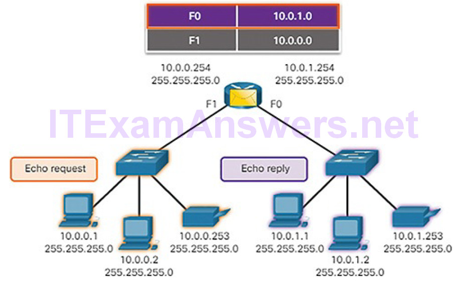
Figure 4-69 The Router Forwards the Echo Request out the F0 Interface
When the remote host responds, the router forwards the Echo Reply back to the local host, as shown in Figure 4-70.
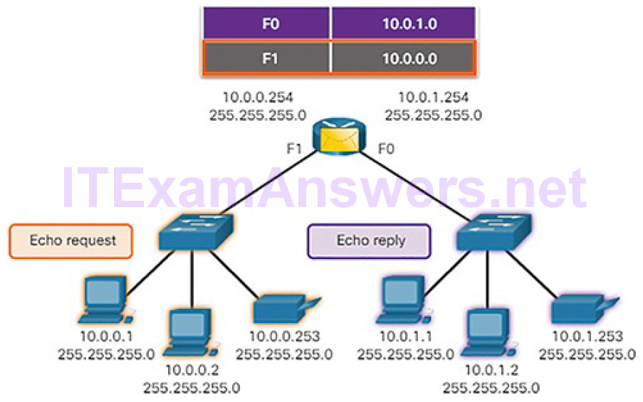
Figure 4-70 The Router Forwards the Echo Reply out the F1 Interface
If this ping is successful, the operation of a large piece of the internetwork can be verified. A successful ping across the internetwork confirms communication on the local network. It also confirms the operation of the router serving as the gateway, and the operation of all other routers that might be in the path between the local network and the network of the remote host.
Additionally, the functionality of the remote host can be verified. If the remote host could not communicate outside of its local network, it would not have responded.
Note
For security reasons, many network administrators limit or prohibit the entry of ICMP messages into the corporate network; therefore, the lack of a ping response could be due to security restrictions.
Traceroute: Testing the Path (4.3.2.4)
Ping is used to test connectivity between two hosts but does not provide information about the details of devices between the hosts. Traceroute (tracert) is a utility that generates a list of hops that were successfully reached along the path. This list can provide important verification and troubleshooting information. If the data reaches the destination, then the trace lists the interface of every router in the path between the hosts. If the data fails at some hop along the way, the address of the last router that responded to the trace can provide an indication of where the problem is, or where security restrictions are found.
Round-Trip Time (RTT)
Using traceroute provides round-trip time for each hop along the path and indicates if a hop fails to respond. The round-trip time is the time a packet takes to reach the remote host and for the response from the host to return. An asterisk (*) is used to indicate a lost or unacknowledged packet.
This information can be used to locate a problematic router in the path. If the display shows high response times or data losses from a particular hop, this is an indication that the resources of the router or its connections may be overloaded.
IPv4 TTL and IPv6 Hop Limit
Traceroute makes use of a function of the TTL field in IPv4 and the Hop Limit field in IPv6 in the Layer 3 headers, along with the ICMP time exceeded message.
Figures 4-71 through 4-78 demonstrate how traceroute takes advantage of TTL.
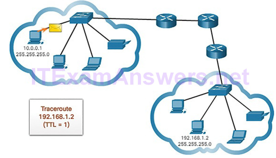
Figure 4-71 Traceroute with One Hop
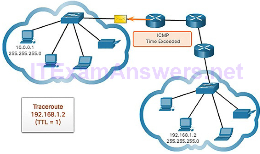
Figure 4-72 Time Exceeded Replay from First Hop
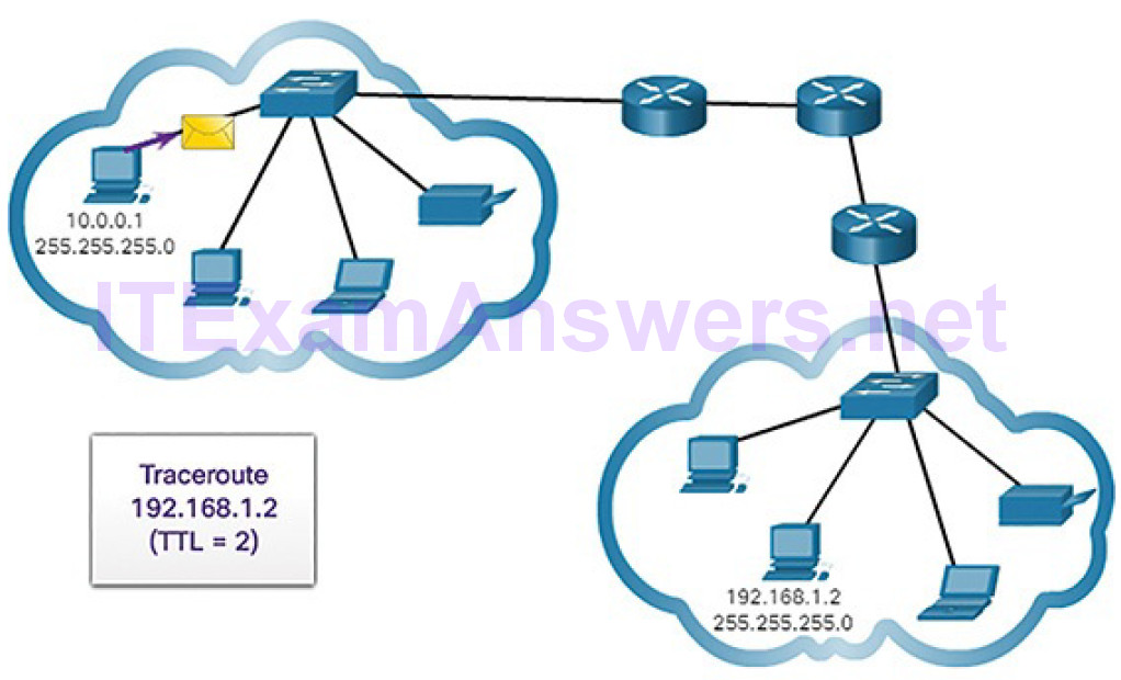
Figure 4-73 Traceroute with Two Hops
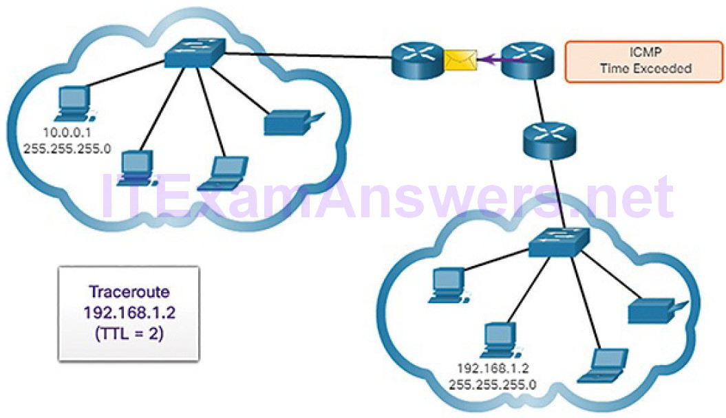
Figure 4-74 Time Exceeded Replay from Second Hop
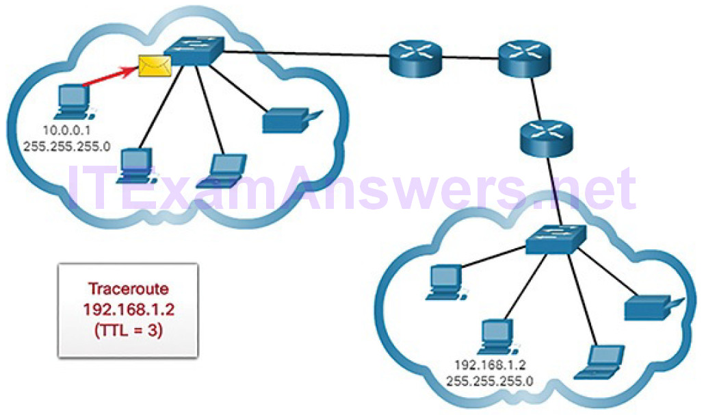
Figure 4-75 Traceroute with Three Hops
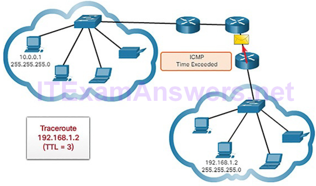
Figure 4-76 Time Exceeded Replay from Third Hop
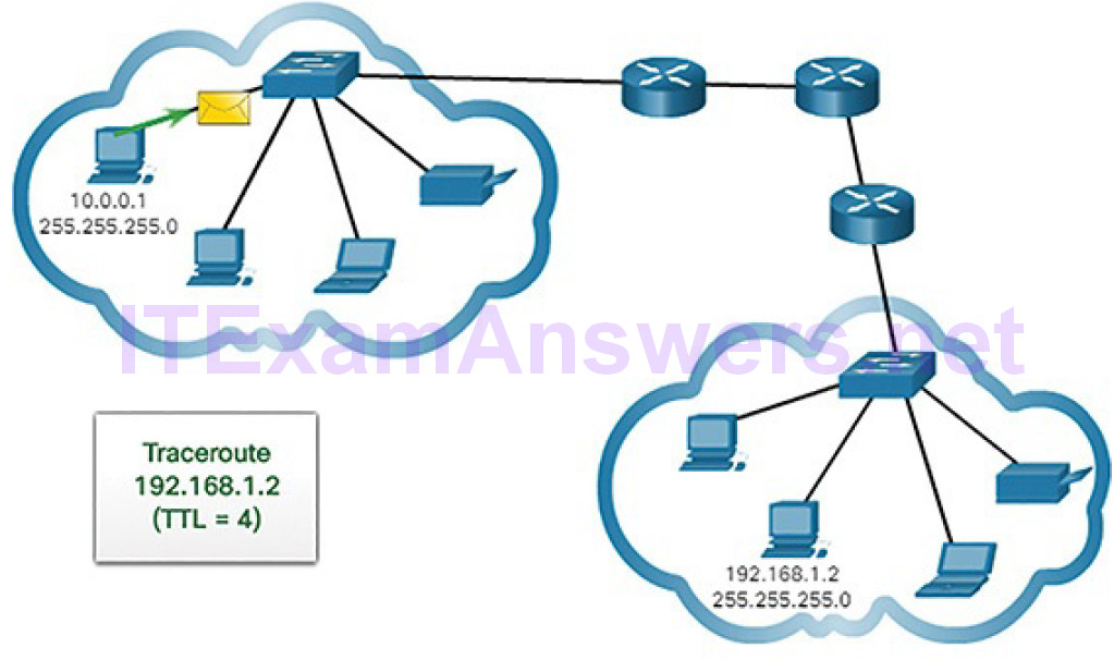
Figure 4-77 Traceroute with Four Hops
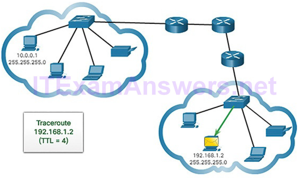
Figure 4-78 Traceroute Reaches Destination
The first sequence of messages sent from traceroute will have a TTL field value of 1 (Figure 4-71). This causes the TTL to time out the IPv4 packet at the first router. This router then responds with an ICMPv4 message (Figure 4-72). Traceroute now has the address of the first hop.
Traceroute then progressively increments the TTL field (2, 3, 4…) for each sequence of messages (Figures 4-73 through 4-76). This provides the trace with the address of each hop as the packets timeout further down the path. The TTL field continues to be increased until the destination is reached, or it is incremented to a predefined maximum.
After the final destination is reached, the host responds with either an ICMP port unreachable message or an ICMP echo reply message instead of the ICMP time exceeded message (Figures 4-77 and 4-78).
ICMP Packet Format (4.3.2.5)
ICMP is encapsulated directly into IP packets. In this sense, it is almost like a transport layer protocol, because it is encapsulated into a packet; however, it is considered to be a Layer 3 protocol. ICMP acts as a data payload within the IP packet. It has a special Header Data field, as shown in Figure 4-79.
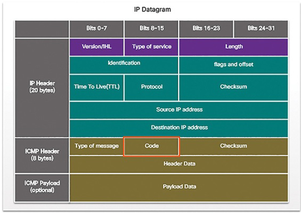
Figure 4-79 IPv4 Datagram
ICMP uses message codes to differentiate between different types of ICMP messages. These are some common message codes:
0: Echo reply (response to a ping)
3: Destination Unreachable
5: Redirect (use another route to your destination)
8: Echo request (for ping)
11: Time Exceeded (TTL became 0)
As you will see later in the course, a cybersecurity analyst knows that the optional ICMP Payload field can be used in an attack vector to exfiltrate data.
Address Resolution Protocol (4.4)
In this section, you will learn how the Address Resolution Protocol enables communication on a network.
MAC and IP (4.4.1)
In this topic, you will learn the roles of the MAC address and the IP address.
Destination on the Same Network (4.4.1.1)
There are two primary addresses assigned to a device on an Ethernet LAN:
- Physical address (the MAC address): This is used for Ethernet NIC to Ethernet NIC communications on the same network.
- Logical address (the IP address): This is used to send the packet from the original source to the final destination.
IP addresses are used to identify the address of the original source device and the final destination device. The destination IP address may be on the same IP network as the source or may be on a remote network.
Note
Most applications use DNS (Domain Name System) to determine the IP address when given a domain name such as www.cisco.com. DNS is discussed in a later chapter.
Layer 2 or physical addresses, like Ethernet MAC addresses, have a different purpose. These addresses are used to deliver the data link frame with the encapsulated IP packet from one NIC to another NIC on the same network. If the destination IP address is on the same network, the destination MAC address will be that of the destination device.
Figure 4-80 shows the Ethernet MAC addresses and IP address for PC A sending an IP packet to the file server on the same network.
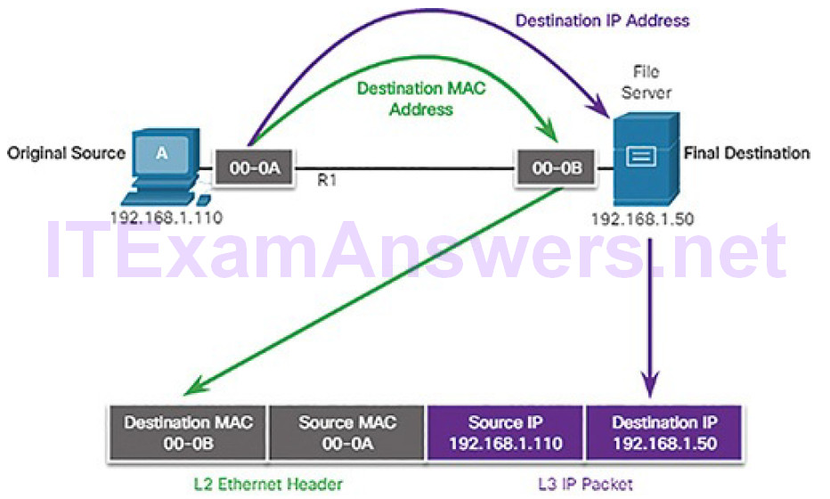
Figure 4-80 Communicating on a Local Network
The Layer 2 Ethernet frame contains:
- Destination MAC address: This is the MAC address of the file server’s Ethernet NIC.
- Source MAC address: This is the MAC address of PC A’s Ethernet NIC.
The Layer 3 IP packet contains:
- Source IP address: This is the IP address of the original source, PC A.
- Destination IP address: This is the IP address of the final destination, the file server.
Destination on a Remote Network (4.4.1.2)
When the destination IP address is on a remote network, the destination MAC address will be the address of the host’s default gateway, which is the router’s NIC, as shown in Figure 4-81.
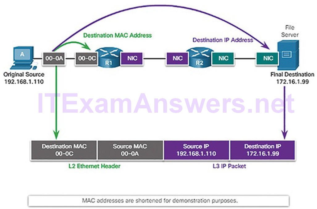
Figure 4-81 Communicating to a Remote Network
Using a postal analogy, this would be similar to a person taking a letter to their local post office. All they need to do is take the letter to the post office and then it becomes the responsibility of the post office to forward the letter on towards its final destination.
Figure 4-81 shows the Ethernet MAC addresses and IPv4 addresses for PC A sending an IP packet to a file server on a remote network. Routers examine the destination IPv4 address to determine the best path to forward the IPv4 packet. This is similar to how the postal service forwards mail based on the address of the recipient.
When the router receives the Ethernet frame, it de-encapsulates the Layer 2 information. Using the destination IP address, it determines the next-hop device, and then encapsulates the IP packet in a new data link frame for the outgoing interface. Along each link in a path, an IP packet is encapsulated in a frame specific to the particular data link technology associated with that link, such as Ethernet. If the next-hop device is the final destination, the destination MAC address will be that of the device’s Ethernet NIC.
How are the IPv4 addresses of the IPv4 packets in a data flow associated with the MAC addresses on each link along the path to the destination? This is donethrough a process called Address Resolution Protocol (ARP).
ARP (4.4.2)
In this topic, you will learn the purpose of ARP.
Introduction to ARP (4.4.2.1)
Recall that every device with an IP address on an Ethernet network also has an Ethernet MAC address. When a device sends an Ethernet frame, it contains these two addresses:
- Destination MAC address: The MAC address of the Ethernet NIC, which will be either the MAC address of the final destination device or the MAC address of the router.
- Source MAC address: The MAC address of the sender’s Ethernet NIC.
To determine the destination MAC address, the device uses ARP, as shown in Figure 4-82. ARP resolves IPv4 addresses to MAC addresses, and maintains a table of mappings.
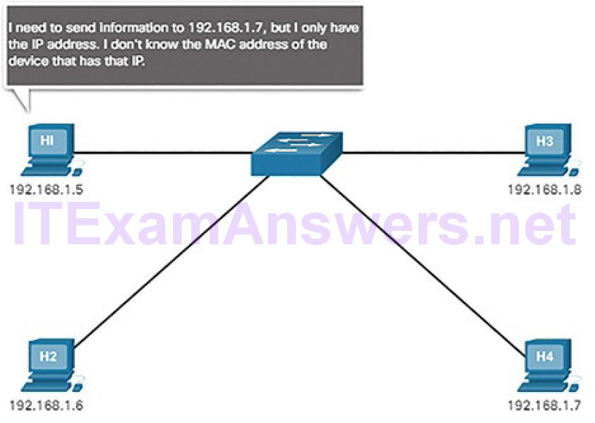
Figure 4-82 H1 Needs the MAC Address for H4
ARP Functions (4.4.2.2)
When a packet is sent to the data link layer to be encapsulated into an Ethernet frame, the device refers to a table in its memory to find the MAC address that is mapped to the IPv4 address. This table is called the ARP table or the ARP cache. The ARP table is stored in the RAM of the device.
The sending device will search its ARP table for a destination IPv4 address and a corresponding MAC address. If the packet’s destination IPv4 address is on the same network as the source IPv4 address, the device will search the ARP table for the destination IPv4 address. If the destination IPv4 address is on a different network than the source IPv4 address, the device will search the ARP table for the IPv4 address of the default gateway.
In both cases, the search is for an IPv4 address and a corresponding MAC address for the device.
Each entry, or row, of the ARP table binds an IPv4 address with a MAC address.
We call the relationship between the two values a map. It simply means that you can locate an IPv4 address in the table and discover the corresponding MAC address. The ARP table temporarily saves (caches) the mapping for the devices on the LAN.
If the device locates the IPv4 address, its corresponding MAC address is used as the destination MAC address in the frame. If no entry is found, then the device sends an ARP request, as shown in Figure 4-83.
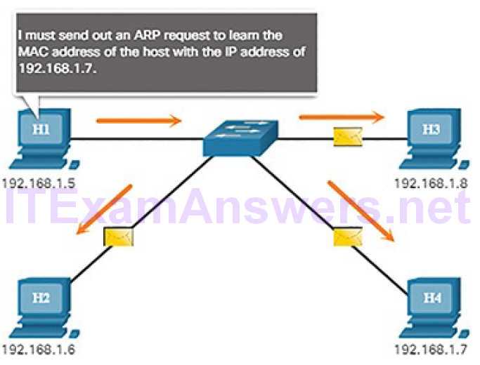
Figure 4-83 H1 Sends an ARP Request
The destination sends an ARP reply, as shown in Figure 4-84.
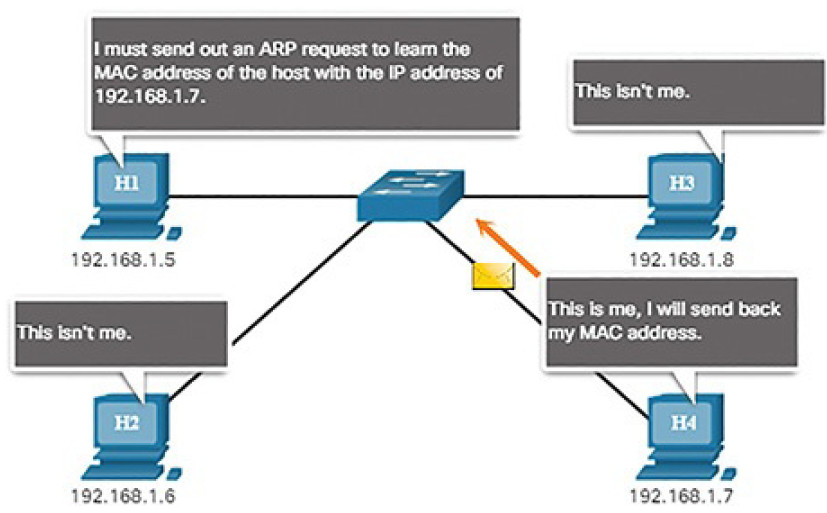
Figure 4-84 H4 Sends an ARP Reply
Video 4.4.2.3: ARP Operation – ARP Request
Refer to the online course to view this video.
Video 4.4.2.4: ARP Operation – ARP Reply
Refer to the online course to view this video.
Video 4.4.2.5: ARP Role in Remote Communication
Refer to the online course to view this video.
Removing Entries from an ARP Table (4.4.2.6)
For each device, an ARP cache timer removes ARP entries that have not been used for a specified period of time. The times differ depending on the device’s operating system. For example, some Windows operating systems store ARP cache entries for 2 minutes, as shown in Figure 4-85.
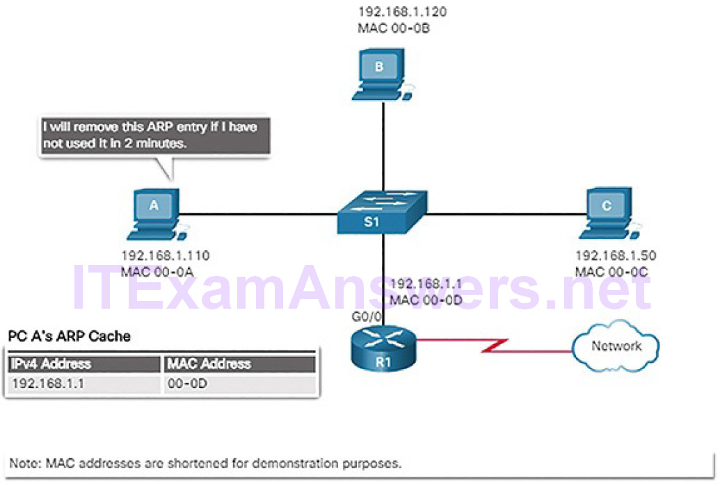
Figure 4-85 Removing MAC-to-IP Address Mappings
Commands may also be used to manually remove all or some of the entries in the ARP table. After an entry has been removed, the process for sending an ARP request and receiving an ARP reply must occur again to enter the map in the ARP table.
ARP Tables on Networking Devices (4.4.2.7)
Network hosts and routers keep ARP tables. ARP information is held in memory on these devices in what is commonly called the ARP cache. The table entries are held for a period of time until they “age out” and are automatically removed from the ARP cache. This ensures the accuracy of the mappings. Holding ARP tables in memory helps to improve network efficiency by decreasing ARP traffic.
The ARP table on a Windows PC can be displayed using the arp -a command, as shown in Example 4-3.
Example 4-3 Host ARP Table
C:\> arp -a

Interface: 192.168.1.67 --- 0xb
Internet Address Physical Address Type
192.168.1.254 64-0f-29-0d-36-91 dynamic
192.168.1.255 ff-ff-ff-ff-ff-ff static
224.0.0.22 01-00-5e-00-00-16 static
224.0.0.251 01-00-5e-00-00-fb static
224.0.0.252 01-00-5e-00-00-fc static
255.255.255.255 ff-ff-ff-ff-ff-ff static

Interface: 10.82.253.91 --- 0x10
Internet Address Physical Address Type
10.82.253.92 64-0f-29-0d-36-91 dynamic
224.0.0.22 01-00-5e-00-00-16 static
224.0.0.251 01-00-5e-00-00-fb static
224.0.0.252 01-00-5e-00-00-fc static
255.255.255.255 ff-ff-ff-ff-ff-ff static
C:\>
Lab 4.4.2.8: Using Wireshark to Examine Ethernet Frames
In this lab, you will complete the following objectives:
- Part 1: Examine the Header Fields in an Ethernet II Frame
- Part 2: Use Wireshark to Capture and Analyze Ethernet Frames
ARP Issues (4.4.3)
In this topic, you will learn how ARP requests impact network and host performance.
ARP Broadcasts (4.4.3.1)
As a broadcast frame, an ARP request is received and processed by every device on the local network. On a typical business network, these broadcasts wouldprobably have minimal impact on network performance. However, if a large number of devices were to be powered up and all start accessing network services at the same time, there could briefly be some reduction in performance, as shown in Figure 4-86. After the devices send out the initial ARP broadcasts and have learned the necessary MAC addresses, any impact on the network will be minimized.
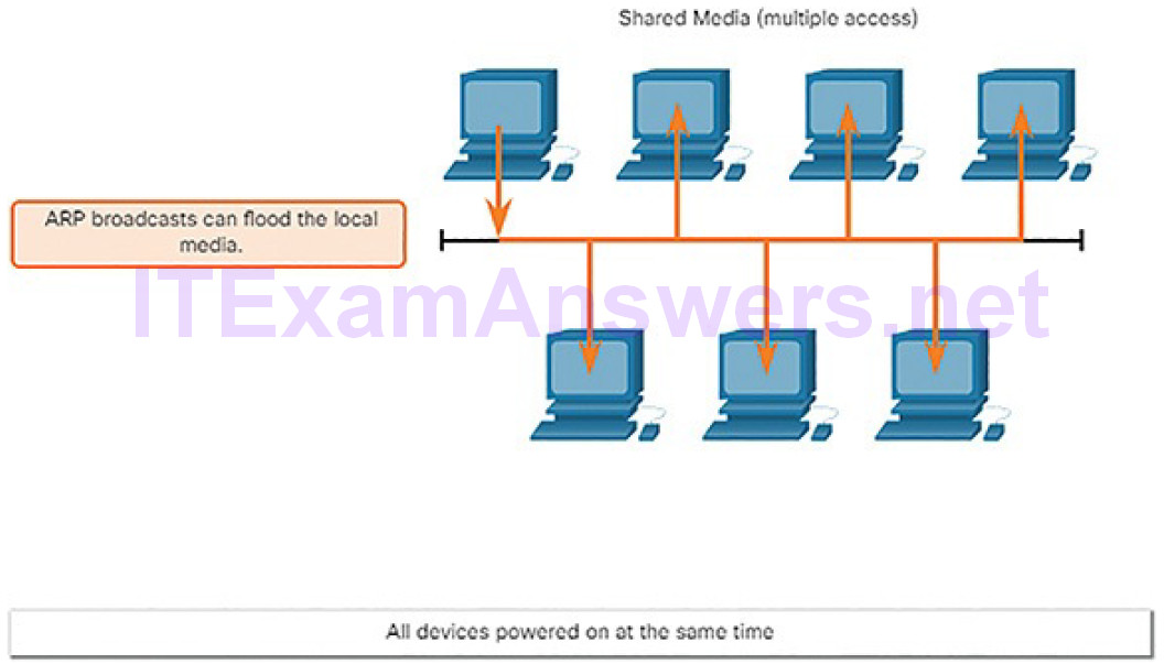
Figure 4-86 ARP Broadcasts and Security
ARP Spoofing (4.4.3.2)
In some cases, the use of ARP can lead to a potential security risk known as ARP spoofing or ARP poisoning. This is a technique used by an attacker to reply to an ARP request for an IPv4 address belonging to another device, such as the default gateway, as shown in Figure 4-87. The attacker sends an ARP reply with its own MAC address. The receiver of the ARP reply will add the wrong MAC address to its ARP table and send these packets to the attacker.
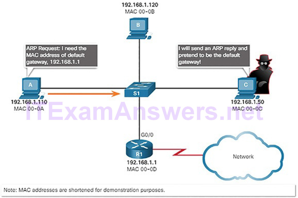
Figure 4-87 All Devices Powered On at the Same Time
ARP vulnerabilities will be discussed in more detail later in the course.
The Transport Layer (4.5)
In this section, you will learn how transport layer protocols support network functionality.
Transport Layer Characteristics (4.5.1)
In this topic, you will learn how transport layer protocols support network communication.
Transport Layer Protocol Role in Network Communication (4.5.1.1)
The transport layer is responsible for establishing a temporary communicationsession between two applications and delivering data between them. An application generates data that is sent from an application on a source host to an application on a destination host. This is without regard to the destination host type, the type of media over which the data must travel, the path taken by the data, the congestion on a link, or the size of the network. As shown in Figure 4-88, the transport layer is the link between the application layer and the lower layers that are responsible for network transmission.
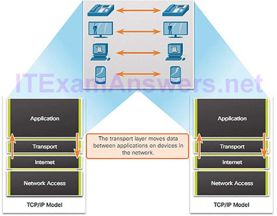
Figure 4-88 Enabling Applications on Devices to Communicate
Tracking Individual Conversations
At the transport layer, each set of data flowing between a source application and a destination application is known as a conversation (Figure 4-89). A host may have multiple applications that are communicating across the network simultaneously. Each of these applications communicates with one or more applications on one or more remote hosts. It is the responsibility of the transport layer to maintain and track these multiple conversations.
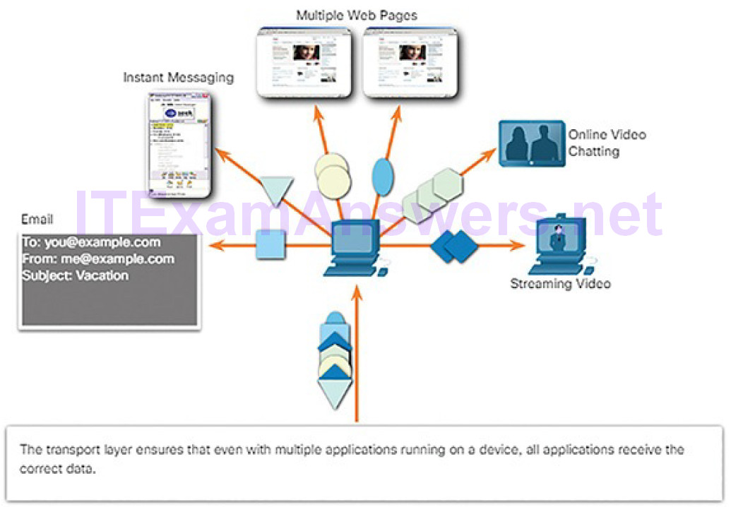
Figure 4-89 Transport Tracks Individual Conversations
Segmenting Data and Reassembling Segments
Data must be prepared to be sent across the media in manageable pieces. Most networks have a limitation on the amount of data that can be included in a single packet. Transport layer protocols have services that segment the application data into blocks that are an appropriate size. This service includes the encapsulation required on each piece of data. A header, used for reassembly, is added to each block of data. This header is used to track the data stream.
At the destination, the transport layer must be able to reconstruct the pieces of data into a complete data stream that is useful to the application layer. The protocols at the transport layer describe how the transport layer header information is used to reassemble the data pieces into streams to be passed to the application layer.
Identifying the Applications
To pass data streams to the proper applications, the transport layer must identify the target application. To accomplish this, the transport layer assigns eachapplication an identifier called a port number. Each software process that needs to access the network is assigned a port number unique to that host.
Transport Layer Mechanisms (4.5.1.2)
Sending some types of data (for example, a streaming video) across a network, as one complete communication stream, can consume all of the available bandwidth. This will then prevent other communications from occurring at the same time. It would also make error recovery and retransmission of damaged data difficult.
Figure 4-90 shows that segmenting the data into smaller chunks enables many different communications, from many different users, to be interleaved (multiplexed) on the same network.
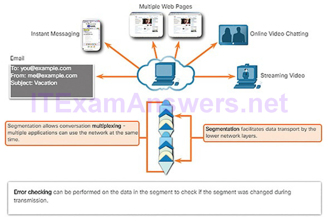
Figure 4-90 Transport Layer Services
To identify each segment of data, the transport layer adds a header containing binary data organized into several fields. It is the values in these fields that enable various transport layer protocols to perform different functions inmanaging data communication.
The transport layer is also responsible for managing reliability requirements of a conversation. Different applications have different transport reliability requirements.
IP is concerned only with the structure, addressing, and routing of packets. IP does not specify how the delivery or transportation of the packets takes place. Transport protocols specify how to transfer messages between hosts. TCP/IP provides two transport layer protocols, Transmission Control Protocol (TCP) and User Datagram Protocol (UDP), as shown in Figure 4-91. IP uses these transport protocols to enable hosts to communicate and transfer data.
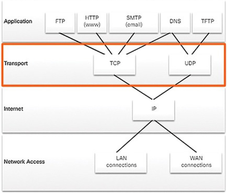
Figure 4-91 Two Transport Layer Protocols
TCP is considered a reliable, full-featured transport layer protocol, which ensures that all of the data arrives at the destination. However, this requires additional fields in the TCP header, which increases the size of the packet and also increases delay. In contrast, UDP is a simpler transport layer protocol that does not provide for reliability. It therefore has fewer fields and is faster than TCP.
TCP Local and Remote Ports (4.5.1.3)
The transport layer must be able to separate and manage multiple communications with different transport requirement needs. Users expect to be able to simultaneously receive and send email and instant messages, view websites, and conduct a VoIP phone call. Each of these applications is sending and receiving data over the network at the same time, despite different reliability requirements. Additionally, data from the phone call is not directed to the web browser, and text from an instant message does not appear in an email.
TCP and UDP manage these multiple simultaneous conversations by using header fields that can uniquely identify these applications. These unique identifiers are the port numbers.
The source port number is associated with the originating application on the local host, as shown in Figure 4-92. The destination port number is associated with the destination application on the remote host.
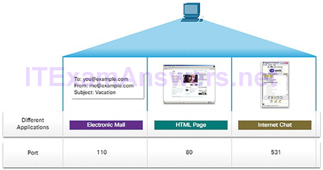
Figure 4-92 Port Number Examples
Source Port
The source port number is dynamically generated by the sending device to identify a conversation between two devices. This process allows multiple conversations to occur simultaneously. It is common for a device to sendmultiple HTTP service requests to a web server at the same time. Each separate HTTP conversation is tracked based on the source ports.
Destination Port
The client places a destination port number in the segment to tell the destination server what service is being requested, as shown in Figure 4-93.
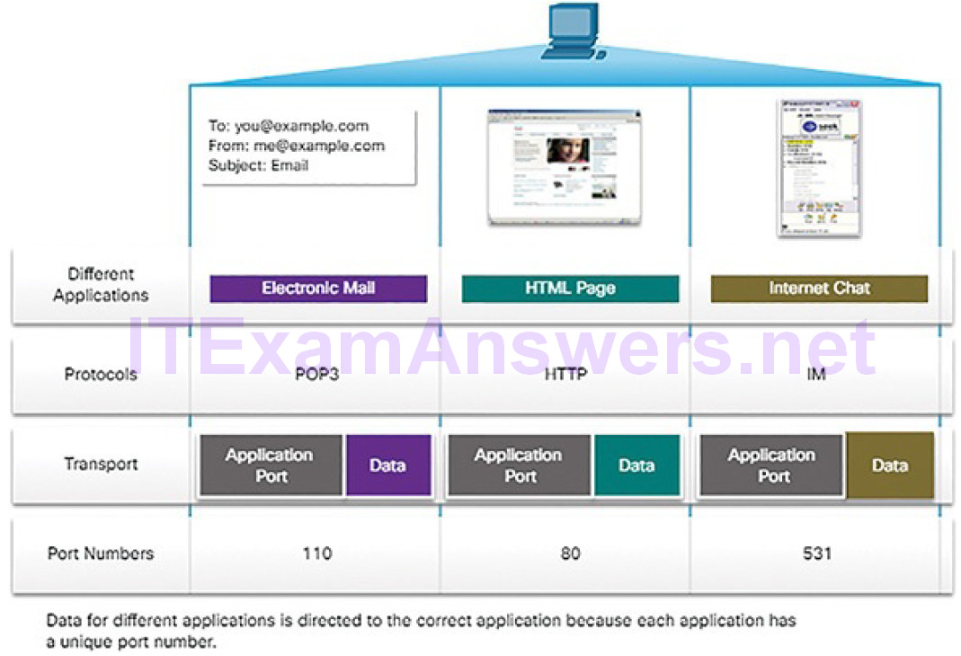
Figure 4-93 Mapping Application Protocols to Port Numbers
For example, when a client specifies port 80 in the destination port, the server that receives the message knows that web services are being requested. A server can offer more than one service simultaneously such as web services on port 80 at the same time that it offers File Transfer Protocol (FTP) connection establishment on port 21.
Socket Pairs (4.5.1.4)
The source and destination ports are placed within the segment, as shown inFigure 4-94.
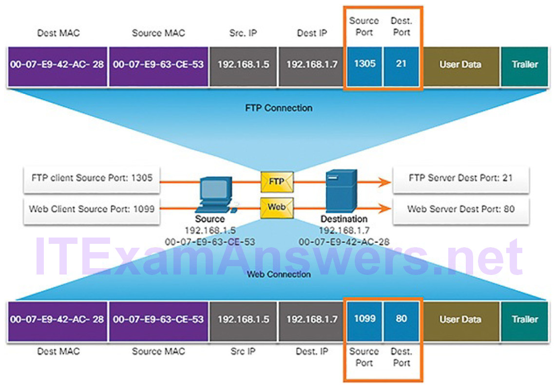
Figure 4-94 Tracking Socket Pairs Between Source and Destination
The segments are then encapsulated within an IP packet. The IP packet contains the IP address of the source and destination. The combination of the source IP address and source port number, or the destination IP address and destination port number, is known as a socket. The socket is used to identify the server and service being requested by the client. A client socket might look like this, with 1099 representing the source port number: 192.168.1.5:1099
The socket on a web server might be: 192.168.1.7:80
Together, these two sockets combine to form a socket pair: 192.168.1.5:1099, 192.168.1.7:80
Sockets enable multiple processes, running on a client, to distinguish themselves from each other, and multiple connections to a server process to be distinguished from each other.
The source port number acts as a return address for the requesting application. The transport layer keeps track of this port and the application that initiated the request so that when a response is returned, it can be forwarded to the correct application.
TCP vs. UDP (4.5.1.5)
For some applications, segments must arrive in a very specific sequence to be processed successfully. With other applications, all data must be fully received before any is considered useful. In both of these instances, TCP is used as the transport protocol. Application developers must choose which transport protocol type is appropriate based on the requirements of the applications.
For example, applications such as databases, web browsers, and email clients require that all data that is sent arrives at the destination in its original condition. Any missing data could cause a corrupt communication that is either incomplete or unreadable. These applications are designed to use TCP.
TCP transport is analogous to sending packages that are tracked from source to destination. If a shipping order is broken up into several packages, a customer can check online to see the order of the delivery.
With TCP, there are three basic operations of reliability:
- Numbering and tracking data segments transmitted to a specific host from a specific application
- Acknowledging received data
- Retransmitting any unacknowledged data after a certain period of time
Figures 4-95 through 4-98 demonstrate how TCP segments and acknowledgments are transmitted between sender and receiver.
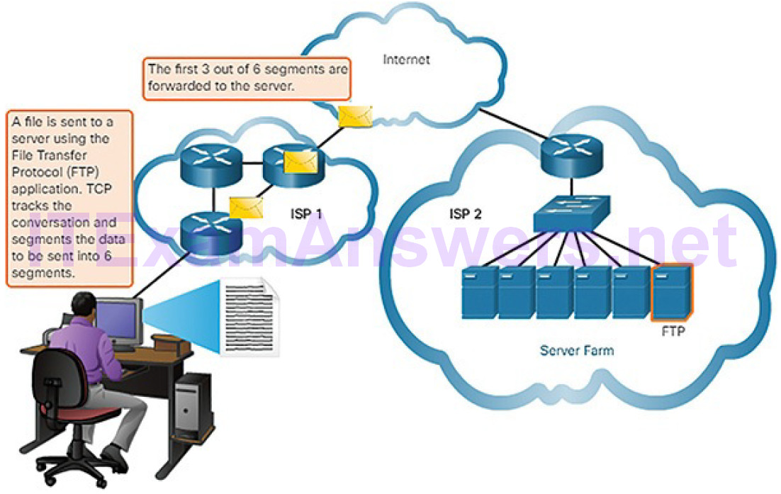
Figure 4-95 Sending Data Using a TCP Application: FTP
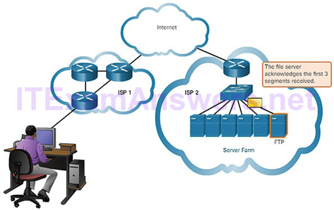
Figure 4-96 Acknowledging Receipt of TCP Application Data
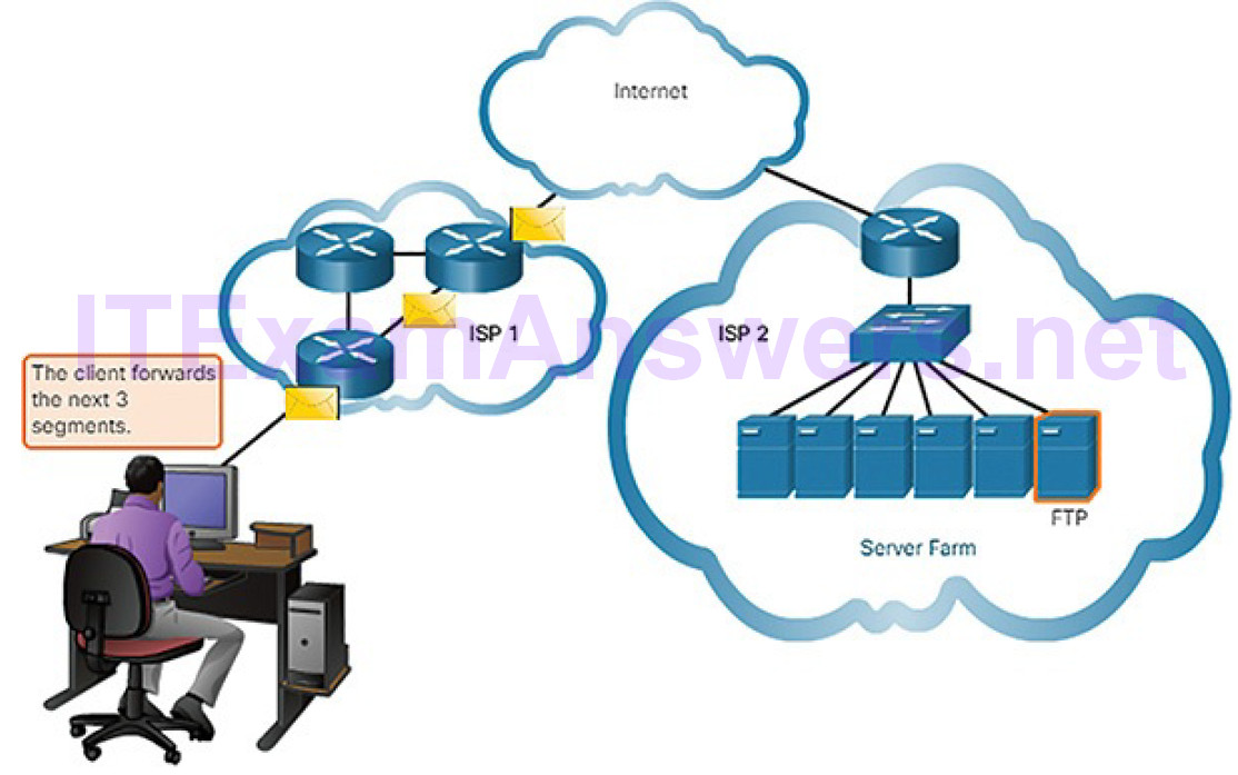
Figure 4-97 Sending More Data Using TCP
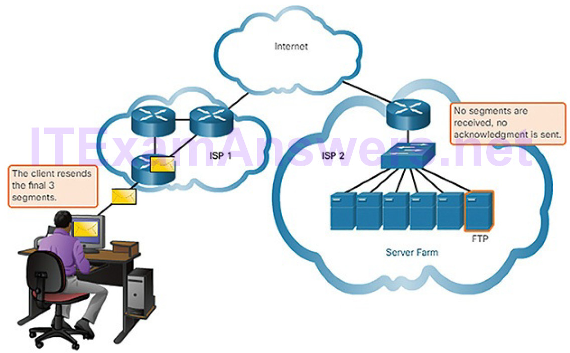
Figure 4-98 No Segments Received at Destination
In other cases, an application can tolerate some data loss during transmission over the network, but delays in transmission are unacceptable. UDP is the better choice for these applications because less network overhead is required. There is a trade-off between the value of reliability and the burden it places on network resources. Adding overhead to ensure reliability for some applications could reduce the usefulness of the application and can even be detrimental. In such cases, UDP is a better transport protocol. UDP is preferable for applications such as streaming live audio, live video, and Voice over IP (VoIP). Acknowledgments and retransmission would slow down delivery.
For example, if one or two segments of a live video stream fail to arrive, it creates a momentary disruption in the stream. This may appear as distortion in the image or sound, but may not be noticeable to the user. If the destination device had to account for lost data, the stream could be delayed while waiting for retransmissions, therefore causing the image or sound to be greatly degraded.
In this case, it is better to render the best media possible with the segments received, and forego reliability.
UDP provides the basic functions for delivering data segments between the appropriate applications, with very little overhead and data checking. UDP is known as a best-effort delivery protocol. In the context of networking, best-effort delivery is referred to as “unreliable” because there is no acknowledgment that the data is received at the destination. With UDP, there are no transport layer processes that inform the sender of a successful delivery.
UDP is similar to placing a regular, non-registered, letter in the mail. The sender of the letter is not aware of the availability of the receiver to receive the letter. Nor is the post office responsible for tracking the letter or informing the sender if the letter does not arrive at the final destination.
Figures 4-99 and 4-100 demonstrate how UDP segments are transmitted from sender to receiver.
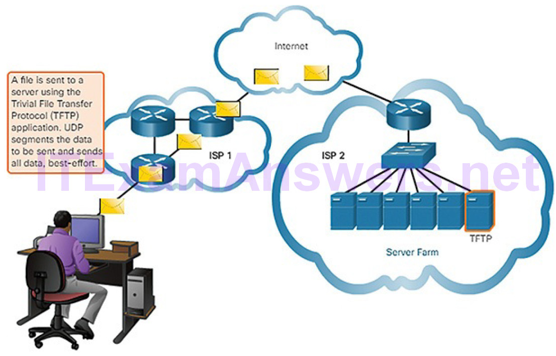
Figure 4-99 Sending Data Using a UDP Application: TFTP
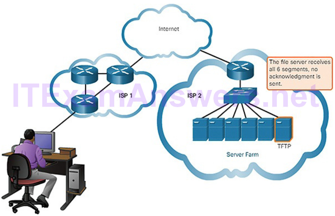
Figure 4-100 No Acknowledgments Sent by Destination
Figure 4-101 provides an overview and comparison of the features of TCP and UDP.
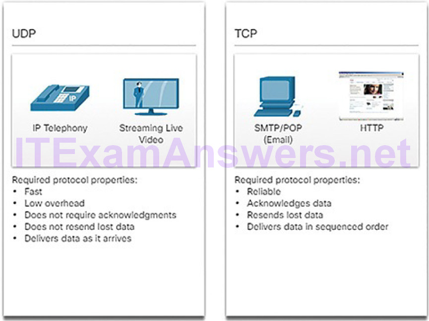
Figure 4-101 Comparing UDP and TCP
Note
Applications that stream stored audio and video use TCP. For example, if your network suddenly cannot support the bandwidth needed to watch an on-demand movie, the application pauses the playback. During the pause, you might see a “buffering…” message while TCP works to re-establish the stream. When all the segments are in order and a minimum level of bandwidth is restored, your TCP session resumes and the movie continues to play.
TCP and UDP Headers (4.5.1.6)
TCP is a stateful protocol. A stateful protocol is a protocol that keeps track of the state of the communication session. To track the state of a session, TCP records which information it has sent and which information has been acknowledged. The stateful session begins with the session establishment and ends when closedwith the session termination.
As shown in Figure 4-102, each TCP segment has 20 bytes of overhead in the header encapsulating the application layer data:
- Source Port (16 bits) and Destination Port (16 bits): These are used to identify the application.
- Sequence Number (32 bits): This is used for data reassembly purposes.
- Acknowledgment Number (32 bits): This indicates the data that has been received.
- Header Length (4 bits): This is known as “data offset.” It indicates the length of the TCP segment header.
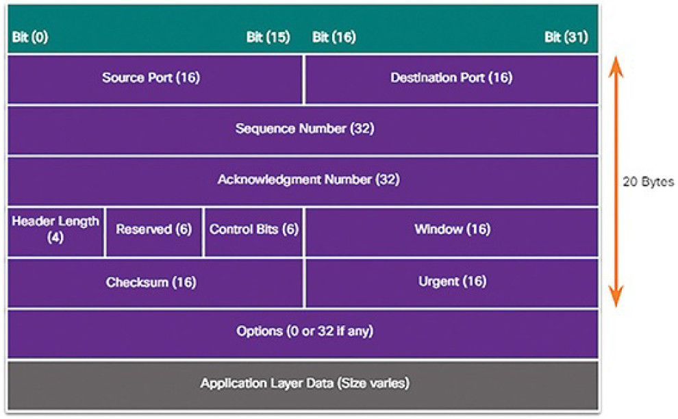
Figure 4-102 TCP Segment Headers
- Reserved (6 bits): This field is reserved for the future.
- Control Bits (6 bits): This includes bit codes, or flags, which indicate the purpose and function of the TCP segment.
- Window (16 bits): This indicates the number of bytes that can be accepted at one time.
- Checksum (16 bits): This is used for error checking of the segment header and data.
- Urgent (16 bits): This indicates if data is urgent.
There are 6 control bits:
- URG: This indicates that the segment should be classified as urgent.
- ACK: This indicates that the Acknowledgment Number field is significant. All segments in an established connection will have this bit set.
- PSH: This is the push function. It indicates that the segment should not be buffered but should be sent immediately to the receiving application.
- RST: This indicates that an unexpected condition has occurred and that the connection should be reset.
- SYN: This is used to initiate a connection. This should only be set in the initial segments in the connection establishment phase of data communication.
- FIN: This signals that no more data will be transferred and that the connection should be terminated.
UDP is a stateless protocol, meaning neither the client nor the server is obligated to keep track of the state of the communication session. If reliability is required when using UDP as the transport protocol, it must be handled by the application.
One of the most important requirements for delivering live video and voice over the network is that the data continues to flow quickly. Live video and voice applications can tolerate some data loss with minimal or no noticeable effect, and are perfectly suited to UDP.
The pieces of communication in UDP are called datagrams, as shown in Figure 4-103. These datagrams are sent as best-effort by the transport layer protocol. UDP has a low overhead of 8 bytes.

Figure 4-103 UDP Segment Headers
Activity 4.5.1.7: Compare TCP and UDP Characteristics
Refer to the online course to complete this Activity.
Transport Layer Operation (4.5.2)
In this topic, you will learn how transport layer protocols operate.
TCP Port Allocation (4.5.2.1)
Each application process running on a server is configured to use a port number, either by default or manually, by a system administrator. An individual server cannot have two services assigned to the same port number within the same transport layer services.
For example, a server running a web server application and a file transfer application cannot have both configured to use the same port (for example, TCP port 80). An active server application assigned to a specific port is considered to be open. This means that the transport layer running on the server accepts and processes segments addressed to that port. Any incoming client request addressed to the correct socket is accepted, and the data is passed to the server application. There can be many ports open simultaneously on a server, one for each active server application.
When establishing a connection with a server, the transport layer on the client establishes a source port to keep track of data sent from the server. Just as a server can have many ports open for server processes, clients can have many ports open for connections to multiple sockets. Local source ports are randomly allocated from a range of numbers that is usually from 49152 to 65535. Segments sent to the client from a server will use the client port number as the destination port for data from the socket.
Refer to Figures 4-104 through 4-108 to see the typical allocation of source and destination ports in TCP client-server operations.
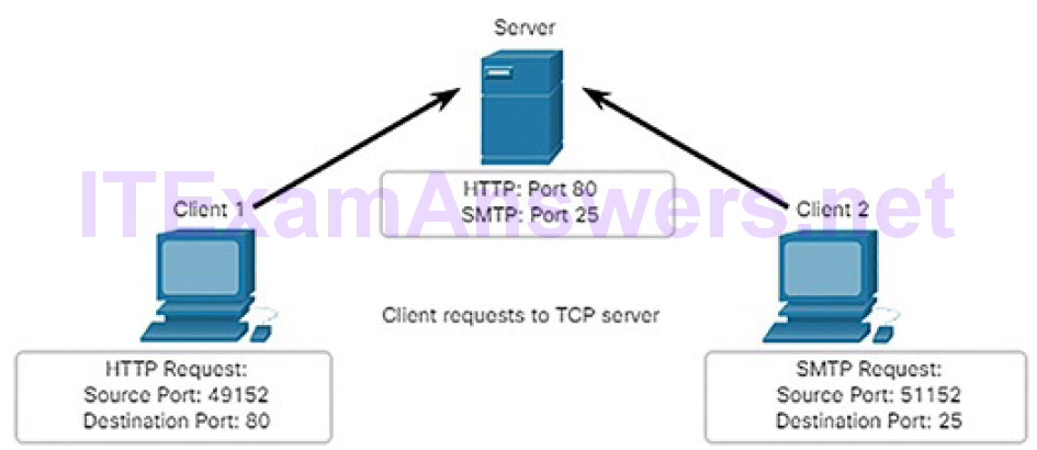
Figure 4-104 Clients Sending TCP Requests
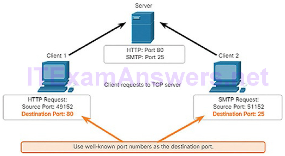
Figure 4-105 Request Destination Ports
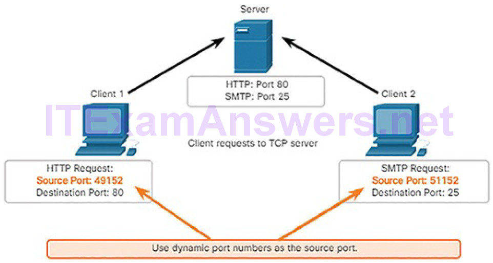
Figure 4-106 Request Source Ports
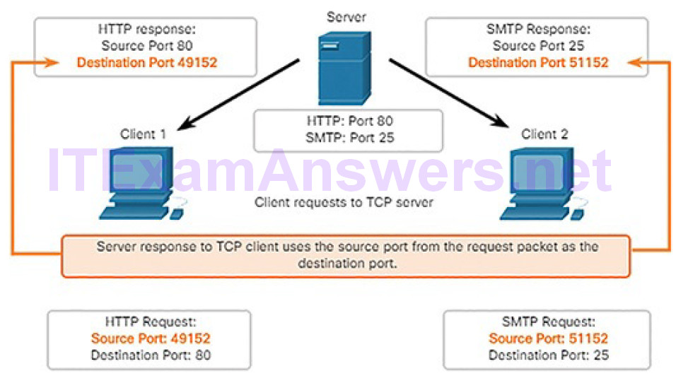
Figure 4-107 Response Destination Ports
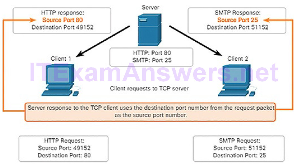
Figure 4-108 Response Source Ports
A TCP Session Part I: Connection Establishment and Termination (4.5.2.2)
In some cultures, when two persons meet, they often greet each other by shaking hands. The act of shaking hands is understood by both parties as a signal for a friendly greeting. Connections on the network are similar. In TCP connections, the host client establishes the connection with the server.
Connection Establishment
Hosts track each data segment within a session and exchange information about what data is received using the information in the TCP header. TCP is a full-duplex protocol, where each connection represents two one-way communication streams or sessions. To establish the connection, the hosts perform a three-way handshake. Control bits in the TCP header indicate the progress and status of the connection.
The three-way handshake accomplishes three things:
- It establishes that the destination device is present on the network.
- It verifies that the destination device has an active service and is accepting requests on the destination port number that the initiating client intends to use.
- It informs the destination device that the source client intends to establish a communication session on that port number.
A TCP connection is established in three steps, as shown in Figure 4-109:
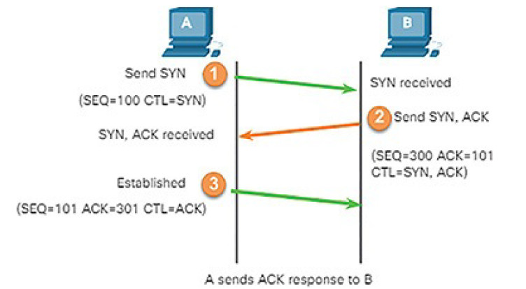
Figure 4-109 TCP Connection Establishment and Termination
1. The initiating client requests a client-to-server communication session with the server.
2. The server acknowledges the client-to-server communication session and requests a server-to-client communication session.
3. The initiating client acknowledges the server-to-client communication session.
Connection Termination
After the communication is completed, the sessions are closed, and the connection is terminated. The connection and session mechanisms enable TCP’s reliability function.
To close a connection, the Finish (FIN) control flag must be set in the segment header. To end each one-way TCP session, a two-way handshake, consisting of a FIN segment and an Acknowledgment (ACK) segment, is used. Therefore, to terminate a single conversation supported by TCP, four exchanges are needed to end both sessions, as shown in Figure 4-110.
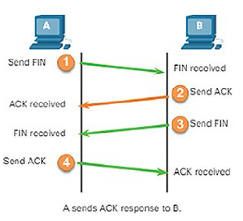
Figure 4-110 TCP Session Termination (FIN)
Note
In this explanation, the terms client and server are used as a reference for simplicity, but the termination process can be initiated by any two hosts that have an open session:
1. When the client has no more data to send in the stream, it sends a segment with the FIN flag set.
2. The server sends an ACK to acknowledge the receipt of the FIN to terminate the session from client to server.
3. The server sends a FIN to the client to terminate the server-to-client session.
4. The client responds with an ACK to acknowledge the FIN from the server.
When all segments have been acknowledged, the session is closed.
The 6 bits in the Control Bits field (Figure 4-111) of the TCP segment header are also known as flags. A flag is a bit that is set to “on” or “off.” For our purposes, four flags are important: SYN, ACK, FIN, and RST. The RST flag is used to reset a connection when an error or timeout occurs.
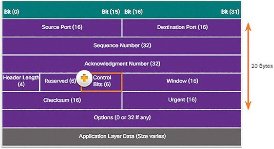
Figure 4-111 The Control Bits Field
Video Demonstration 4.5.2.3: TCP 3-Way Handshake
Refer to the online course to view this video.
Lab 4.5.2.4: Using Wireshark to Observe the TCP 3-Way Handshake
In this lab, you will complete the following objectives:
- Part 1: Prepare the Hosts to Capture the Traffic
- Part 2: Analyze the Packets Using Wireshark
- Part 3: View the Packets Using tcpdump
Activity 4.5.2.5: TCP Connection and Termination Process
Refer to the online course to complete this Activity.
A TCP Session Part II: Data Transfer (4.5.2.6)
TCP Ordered Delivery TCP segments may arrive at their destination out of order. For the original message to be understood by the recipient, the data in these segments is reassembled into the original order. Sequence numbers are assigned in the header of each packet to achieve this goal. The sequence number represents the first data byte of the TCP segment.
During session setup, an initial sequence number (ISN) is set. This ISN represents the starting value of the bytes for this session that is transmitted to the receiving application. As data is transmitted during the session, the sequence number is incremented by the number of bytes that have been transmitted. This data byte tracking enables each segment to be uniquely identified and acknowledged. Missing segments can then be identified.
Note
The ISN does not begin at 1 but instead is a random number. This is to prevent certain types of malicious attacks. For simplicity, we will use an ISN of 1 for the examples in this chapter.
Segment sequence numbers indicate how to reassemble and reorder received segments, as shown in Figure 4-112.
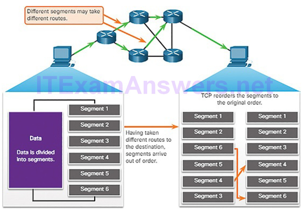
Figure 4-112 TCP Segments Are Reordered at the Destination
The receiving TCP process places the data from a segment into a receiving buffer. Segments are placed in the proper sequence order and passed to the application layer when reassembled. Any segments that arrive with sequence numbers that are out of order are held for later processing. Then, when the segments with the missing bytes arrive, these segments are processed in order.
Flow Control
TCP also provides mechanisms for flow control, which is the amount of data that the destination can receive and process reliably. Flow control helps maintain the reliability of TCP transmission by adjusting the rate of data flow between source and destination for a given session. To accomplish this, the TCP header includes a 16-bit field called the window.
Figure 4-113 shows an example of window size and acknowledgments.
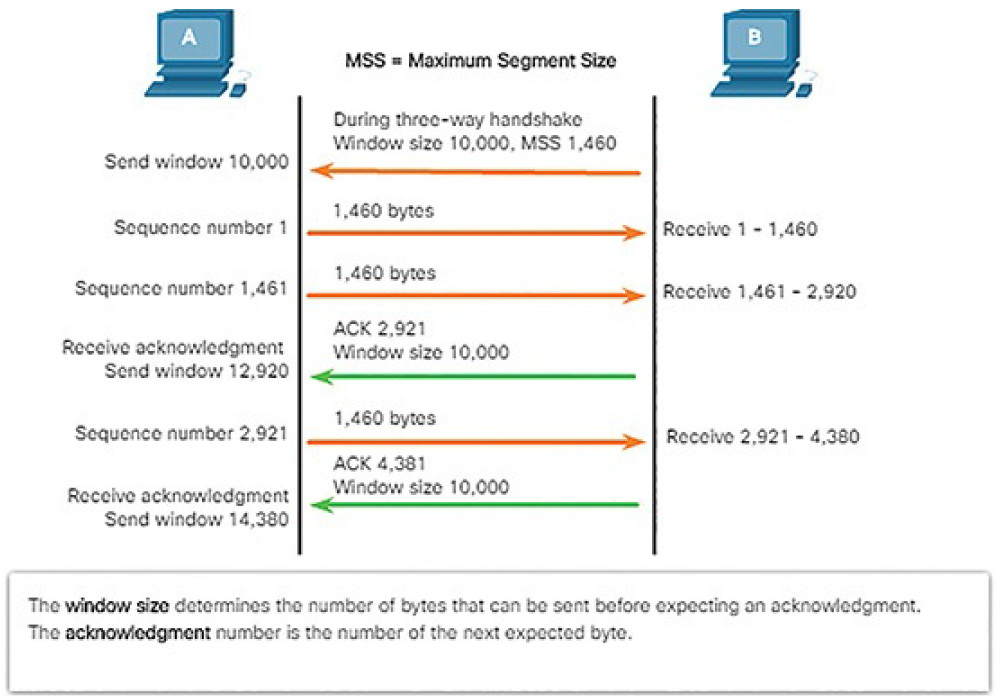
Figure 4-113 TCP Window Size Example
The window size is the number of bytes that the destination device of a TCP session can accept and process at one time. In this example, PC B’s initial window size for the TCP session is 10,000 bytes. Starting with the first byte, byte number 1, the last byte PC A can send without receiving an acknowledgment is byte 10,000. This is known as PC A’s send window. The window size is included in every TCP segment so the destination can modify the window size at any time depending on buffer availability.
Note
In Figure 4-113, the source is transmitting 1460 bytes of data within each TCP segment. This is known as the MSS (Maximum Segment Size).
The initial window size is agreed upon when the TCP session is established during the three-way handshake. The source device must limit the number of bytes sent to the destination device based on the destination’s window size. Only after the source device receives an acknowledgment that the bytes have been received can it continue sending more data for the session. Typically, the destination will not wait for all the bytes for its window size to be receivedbefore replying with an acknowledgment. As the bytes are received and processed, the destination will send acknowledgments to inform the source that it can continue to send additional bytes.
The process of the destination sending acknowledgments as it processes bytes received and the continual adjustment of the source’s send window is known as sliding windows.
If the availability of the destination’s buffer space decreases, it may reduce its window size and inform the source to reduce the number of bytes it should send without receiving an acknowledgment.
A useful discussion of TCP sequence and acknowledgment numbers can be found here.
Video Demonstration 4.5.2.7: Sequence Numbers and Acknowledgments
Refer to the online course to view this video.
Video Demonstration 4.5.2.8: Data Loss and Retransmission
Refer to the online course to view this video.
A UDP Session (4.5.2.9)
Like segments with TCP, when UDP datagrams are sent to a destination, they often take different paths and arrive in the wrong order. UDP does not track sequence numbers the way TCP does. UDP has no way to reorder the datagrams into their transmission order.
Therefore, UDP simply reassembles the data in the order that it was received and forwards it to the application, as shown in Figure 4-114. If the data sequence is important to the application, the application must identify the proper sequence and determine how the data should be processed.
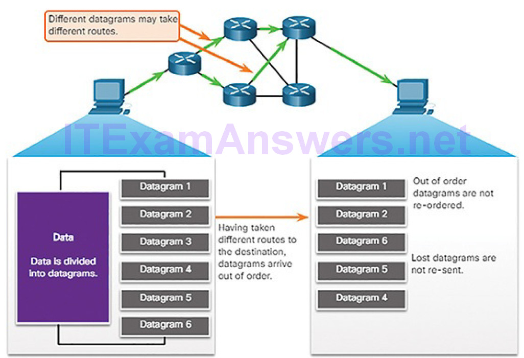
Figure 4-114 UDP Is Connectionless and Unreliable
Like TCP-based applications, UDP-based server applications are assigned well-known or registered port numbers, as shown in Figure 4-115.
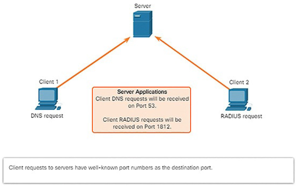
Figure 4-115 UDP Server Listening for Requests
When these applications or processes are running on a server, they accept the data matched with the assigned port number. When UDP receives a datagram destined for one of these ports, it forwards the application data to the appropriate application based on its port number.
Note
The Remote Authentication Dial-in User Service (RADIUS) server shown in Figure 4-115 provides authentication, authorization, and accounting services to manage user access.
As with TCP, client-server communication is initiated by a client application that requests data from a server process. The UDP client process dynamically selects a port number from the range of port numbers and uses this as the source port for the conversation. The destination port is usually the well-known or registered port number assigned to the server process.
After a client has selected the source and destination ports, the same pair of ports is used in the header of all datagrams used in the transaction. For the data returning to the client from the server, the source and destination port numbers in the datagram header are reversed.
Port scanning is usually part of a reconnaissance attack. There are a variety of port scanning methods that can be used. We will explore how to use the Nmap utility. Nmap is a powerful network utility that is used for network discovery and security auditing.
Network Services (4.6)
In this section, you will learn how network services enable network functionality.
DHCP (4.6.1)
In this topic, you will learn how DHCP services enable network functionality.
DHCP Overview (4.6.1.1)
The Dynamic Host Configuration Protocol (DHCP) for IPv4 service automates the assignment of IPv4 addresses, subnet masks, gateways, and other IPv4 networking parameters. This is referred to as dynamic addressing. The alternative to dynamic addressing is static addressing. When using static addressing, the network administrator manually enters IP address information on hosts. DHCPv6 (DHCP for IPv6) provides similar services for IPv6 clients.
When an IPv4, DHCP-configured device boots up or connects to the network, the client broadcasts a DHCP discover (DHCPDISCOVER) message to identify any available DHCP servers on the network. A DHCP server replies with a DHCP offer (DHCPOFFER) message, which offers a lease to the client, as
shown in Figure 4-116.

Figure 4-116 Dynamic Host Configuration Protocol (DHCP)
The offer message contains the IPv4 address and subnet mask to be assigned, the IPv4 address of the DNS server, and the IPv4 address of the default gateway. The lease offer also includes the duration of the lease.
The client may receive multiple DHCPOFFER messages if there is more than one DHCP server on the local network. Therefore, it must choose between them, and sends a DHCP request (DHCPREQUEST) message that identifies the explicit server and lease offer that the client is accepting. A client may also choose to request an address that it had previously been allocated by the server.
Assuming that the IPv4 address requested by the client, or offered by the server, is still available, the server returns a DHCP acknowledgment (DHCPACK)message that acknowledges to the client that the lease has been finalized. If the offer is no longer valid, then the selected server responds with a DHCP negative acknowledgment (DHCPNAK) message. If a DHCPNAK message is returned, then the selection process must begin again with a new DHCPDISCOVER message being transmitted. After the client has the lease, it must be renewed prior to the lease expiration through another DHCPREQUEST message. Figures 4-117 and 4-118 illustrate the steps in DHCPv4 operation.
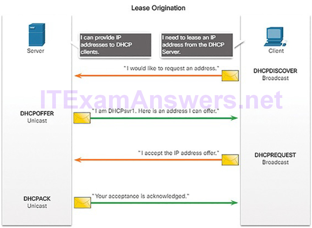
Figure 4-117 DHCPv4 Operation: Lease Origination
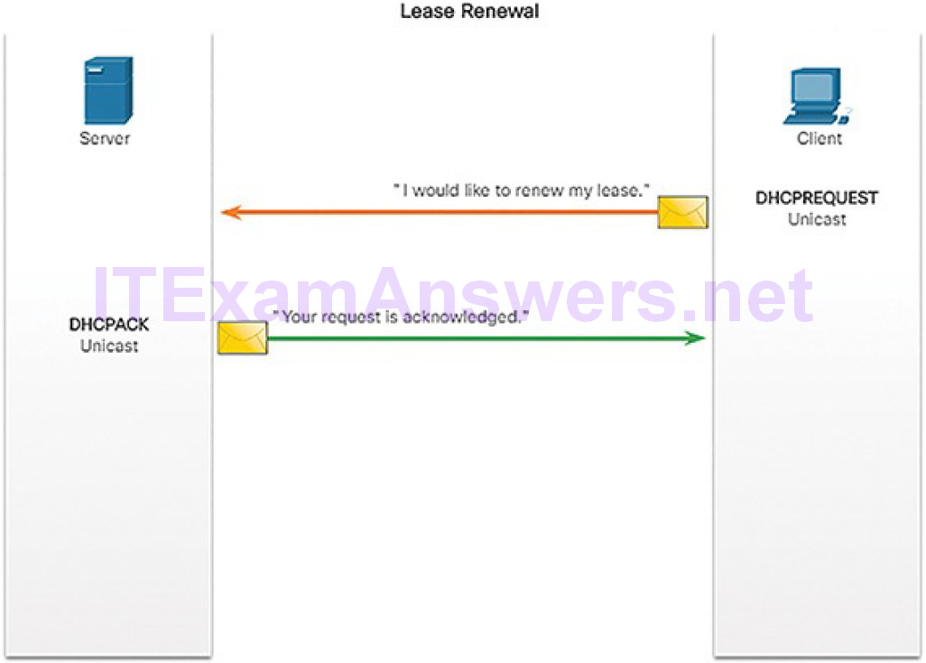
Figure 4-118 DHCPv4 Operation: Lease Renewal
The DHCP server ensures that all IP addresses are unique (the same IP address cannot be assigned to two different network devices simultaneously). Most Internet providers use DHCP to allocate addresses to their customers.
DHCPv6 has similar set of messages to those used for DHCP for IPv4. The DHCPv6 messages are SOLICIT, ADVERTISE, INFORMATION REQUEST, and REPLY.
DHCPv4 Message Format (4.6.1.2)
The DHCPv4 message format is used for all DHCPv4 transactions. DHCPv4 messages are encapsulated within the UDP transport protocol. DHCPv4 messages sent from the client use UDP source port 68 and destination port 67. DHCPv4 messages sent from the server to the client use UDP source port 67 and destination port 68.
Figure 4-119 shows the format of a DHCPv4 message with the following fields:
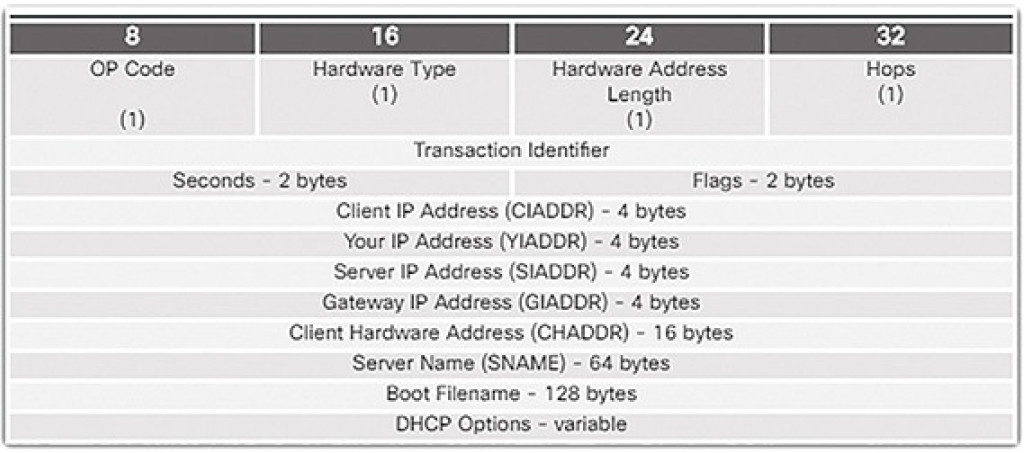
Figure 4-119 DHCPv4 Header Fields
- Operation (OP) Code: Specifies the general type of message. A value of 1 indicates a request message; a value of 2 is a reply message.
- Hardware Type: Identifies the type of hardware used in the network. For example, 1 is Ethernet, 15 is Frame Relay, and 20 is a serial line. These are the same codes used in ARP messages.
- Hardware Address Length: Specifies the length of the address.
- Hops: Controls the forwarding of messages. Set to 0 by a client before transmitting a request.
- Transaction Identifier: Used by the client to match the request with replies received from DHCPv4 servers.
- Seconds: Identifies the number of seconds elapsed since a client began attempting to acquire or renew a lease. Used by DHCPv4 servers to prioritize replies when multiple client requests are outstanding.
- Flags: Used by a client that does not know its IPv4 address when it sends a request. Only one of the 16 bits is used, which is the broadcast flag. A value of 1 in this field tells the DHCPv4 server or relay agent receiving the request that the reply should be sent as a broadcast.
- Client IP Address: Used by a client during lease renewal when the address of the client is valid and usable, not during the process of acquiring an address. The client puts its own IPv4 address in this field if and only if it has a valid IPv4 address while in the bound state; otherwise, it sets the field to 0.
- Your IP Address: Used by the server to assign an IPv4 address to the client.
- Server IP Address: Used by the server to identify the address of the server that the client should use for the next step in the bootstrap process, which may or may not be the server sending this reply. The sending server always includes its own IPv4 address in a special field called the Server Identifier DHCPv4 option.
- Gateway IP Address: Routes DHCPv4 messages when DHCPv4 relay agents are involved. The gateway address facilitates communications of DHCPv4 requests and replies between the client and a server that are on different subnets or networks.
- Client Hardware Address: Specifies the physical layer of the client.
- Server Name: Used by the server sending a DHCPOFFER or DHCPACK message. The server may optionally put its name in this field. This can be a simple text nickname or a DNS domain name, such as dhcpserver.netacad.net.
- Boot Filename: Optionally used by a client to request a particular type of boot file in a DHCPDISCOVER message. Used by a server in a DHCPOFFER to fully specify a boot file directory and filename.
- DHCP Options: Holds DHCP options, including several parameters required for basic DHCP operation. This field is variable in length. Both client and server may use this field.
DNS (4.6.2)
In this topic, you will learn how DNS services enable network functionality.
DNS Overview (4.6.2.1)
The web servers that we so often connect to using names like www.cisco.com are actually reached by assigning IP addresses to packets. On the Internet, these domain names are much easier for people to remember than 198.133.219.25, which is the actual numeric IP address for this server. If Cisco decides to change the numeric address of www.cisco.com, it is transparent to the user because the domain name remains the same. The new address is simply linked to the existingdomain name and connectivity is maintained.
The Domain Name System (DNS) was developed to provide a reliable means of managing and providing domain names and their associated IP addresses. DNS consists of a global hierarchy of distributed servers that contain databases of name to IP address mappings. The client computer in Figure 4-120 will send a request to the DNS server to get the IP address for www.cisco.com.
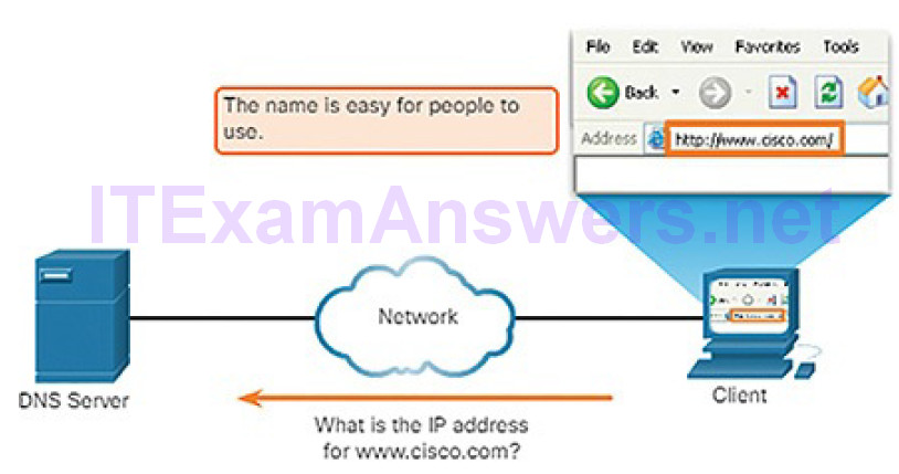
Figure 4-120 DNS Resolves Names to IP Addresses
A recent analysis of network security threats discovered that over 90% of the malicious software that is used to attack networks uses the DNS system to carry out attack campaigns. A cybersecurity analyst should have a thorough understanding of the DNS system and the ways in which malicious DNS traffic can be detected through protocol analysis and the inspection of DNS monitoring information.
The DNS Domain Hierarchy (4.6.2.2)
The DNS consists of a hierarchy of generic top-level domains (gTLDs) which consist of .com, .net, .org, .gov, .edu, and numerous country-level domains, such as .br (Brazil), .es (Spain), .uk (United Kingdom), etc. At the next level of the DNS hierarchy are second-level domains. These are represented by a domain name that is followed by a top-level domain. Subdomains are found at the next level of the DNS hierarchy and represent some division of the second-level domain. Finally, a fourth level can represent a host in a subdomain. Each element of a domain specification is sometimes called a label. The labels movefrom the top of the hierarchy downward from right to left. A dot (“.”) at the end of a domain name represents the root server at the top of the hierarchy. Figure 4-121 illustrates this DNS domain hierarchy.
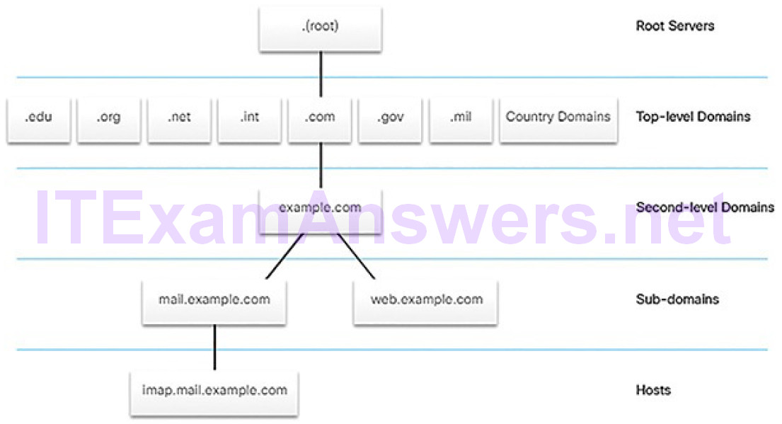
Figure 4-121 DNS Domain Hierarchy
The DNS Lookup Process (4.6.2.3)
To understand DNS, cybersecurity analysts should be familiar with the following terms:
- Resolver: A DNS client that sends DNS messages to obtain information about the requested domain name space.
- Recursion: The action taken when a DNS server is asked to query on behalf of a DNS resolver.
- Authoritative server: A DNS server that responds to query messages with information stored in Resource Records (RRs) for a domain name space stored on the server.
- Recursive resolver: A DNS server that recursively queries for the information asked in the DNS query.
- FQDN: A fully qualified domain name is the absolute name of a devicewithin the distributed DNS database.
- RR: A resource record is a format used in DNS messages that is composed of the following fields: NAME, TYPE, CLASS, TTL, RDLENGTH, and RDATA.
- DNS Zone: A database that contains information about the domain name space stored on an authoritative server.
When attempting to resolve a name to an IP address, a user host, known in the system as a resolver, will first check its local DNS cache. If the mapping is not found there, a query will be issued to the DNS server or servers that are configured in the network addressing properties for the resolver. These servers may be present at an enterprise or ISP. If the mapping is not found there, the DNS server will query other higher-level DNS servers that are authoritative for the top-level domain in order to find the mapping. These are known as recursive queries.
Because of the potential burden on authoritative top-level domain servers, some DNS servers in the hierarchy maintain caches of all DNS records that they have resolved for a period of time. These caching DNS servers can resolve recursive queries without forwarding the queries to higher-level servers. If a server requires data for a zone, it will request a transfer of that data from an authoritative server for that zone. The process of transferring blocks of DNS data between servers is known as a zone transfer.
Figures 4-122 through 4-127 display the steps involved in DNS resolution.
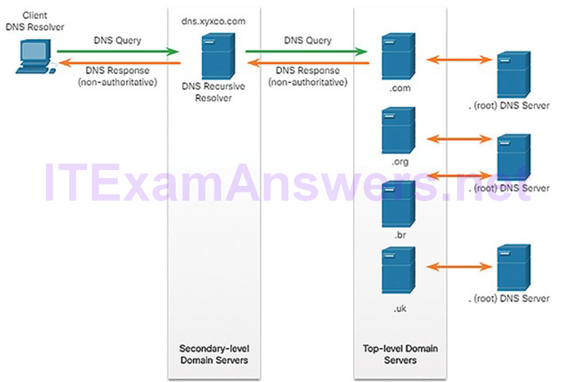
Figure 4-122 Example of the DNS Lookup Process
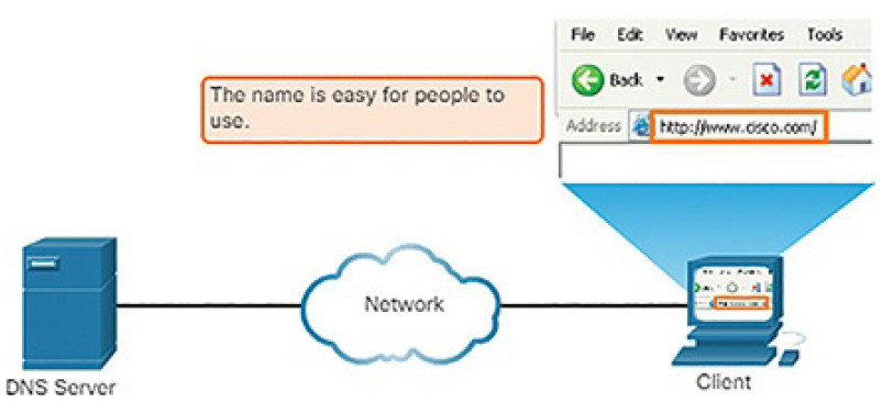
Figure 4-123 Resolving DNS Addresses: Step 1
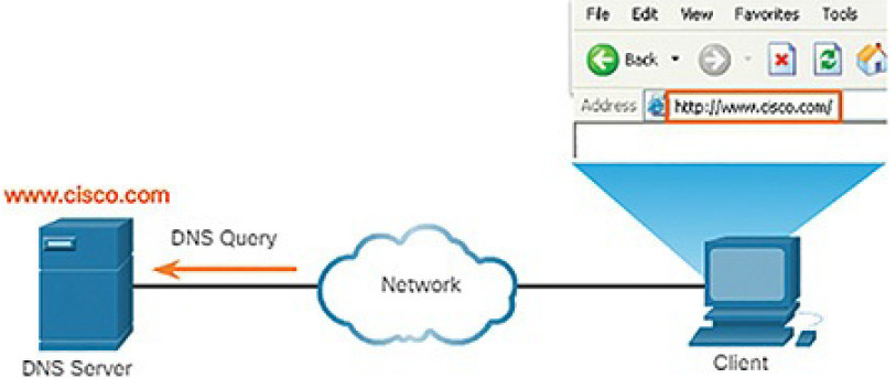
Figure 4-124 Resolving DNS Addresses: Step 2
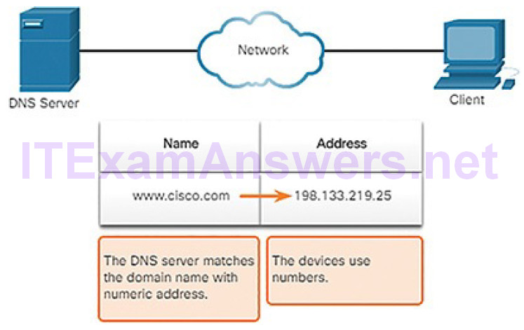
Figure 4-125 Resolving DNS Addresses: Step 3

Figure 4-126 Resolving DNS Addresses: Step 4

Figure 4-127 Resolving DNS Addresses: Step 5
DNS Message Format (4.6.2.4)
DNS uses UDP port 53 for DNS queries and responses. DNS queries originate at a client and responses are issued from DNS servers. If a DNS response exceeds 512 bytes, TCP port 53 is used to handle the message. It includes the format for queries, responses, and data. The DNS protocol communications use a single format called a message. This message format, shown in Figure 4-128, is used for all types of client queries and server responses, error messages, and the transfer of resource record information between servers.

Figure 4-128 DNS Headers
The DNS server stores different types of RRs used to resolve names. These records contain the name, address, and type of record. Here is a list of some of these record types:
- A: An end device IPv4 address
- NS: An authoritative name server
- AAAA: An end device IPv6 address (pronounced quad-A)
- MX: A mail exchange record
When a client makes a query, the server’s DNS process first looks at its own records to resolve the name. If it is unable to resolve the name using its stored records, it contacts other servers to resolve the name. After a match is found and returned to the original requesting server, the server temporarily stores the numbered address in the event that the same name is requested again.
The DNS Client service on Windows PCs also stores previously resolved names in memory. The ipconfig /displaydns command displays all of the cached DNS entries.
Dynamic DNS (4.6.2.5)
DNS requires registrars to accept and distribute DNS mappings from organizations that wish to register domain name and IP address mappings. After the initial mapping has been created, a process which can take 24 hours or more, changes to the IP address that is mapped to the domain name can be made by contacting the registrar or using an online form to the make the change.
However, because of the time it takes for this process to occur and the new mapping to be distributed in DNS, the change can take hours before the new mapping is available to resolvers. In situations in which an ISP is using DHCP to provide addresses to a domain, it is possible that the address that is mapped to the domain could expire and a new address be granted by the ISP. This would result in a disruption of connectivity to the domain through DNS. A new approach was necessary to allow organizations to make fast changes to the IP address that is mapped to a domain.
Dynamic DNS (DDNS) allows a user or organization to register an IP address with a domain name as in DNS. However, when the IP address of the mapping changes, the new mapping can be propagated through the DNS almost instantaneously. For this to occur, a user obtains a subdomain from a DDNS provider. That subdomain is mapped to the IP address of the user’s server, or home router connection to the Internet. Client software runs on either the router or a host PC that detects a change in the Internet IP address of the user. When a change is detected, the DDNS provider is immediately informed of the change and the mapping between the user’s subdomain and the Internet IP address is immediately updated, as shown in Figure 4-129.
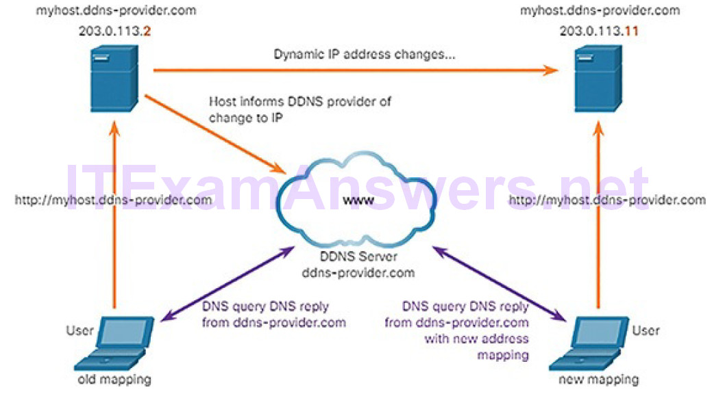
Figure 4-129 Example of Dynamic DNS Process
DDNS does not use a true DNS entry for a user’s IP address. Instead, it acts as an intermediary. The DDNS provider’s domain is registered with the DNS, but the subdomain is mapped to a totally different IP address. The DDNS provider service supplies that IP address to the resolver’s second level DNS server. That DNS server, either at the organization or ISP, provides the DDNS IP address to the resolver.
The WHOIS Protocol (4.6.2.6)
WHOIS is a TCP-based protocol that is used to identify the owners of Internet domains through the DNS system. When an Internet domain is registered and mapped to an IP address for the DNS system, the registrant must supply information regarding who is registering the domain. The WHOIS application uses a query, in the form of an FQDN. The query is issued through a WHOIS service or application. The official ownership registration record is returned to the user by the WHOIS service. This can be useful for identifying the destinations that have been accessed by hosts on a network. WHOIS has limitations, and hackers have ways of hiding their identities. However, WHOIS is a starting point for identifying potentially dangerous Internet locations that may have been reached through the network. An Internet-based WHOIS service is maintained by ICANN and can be reached at https://whois.icann.org/, asshown in Figure 4-130. Other WHOIS services are maintained by Regional Internet Registries such as RIPE and APNIC.
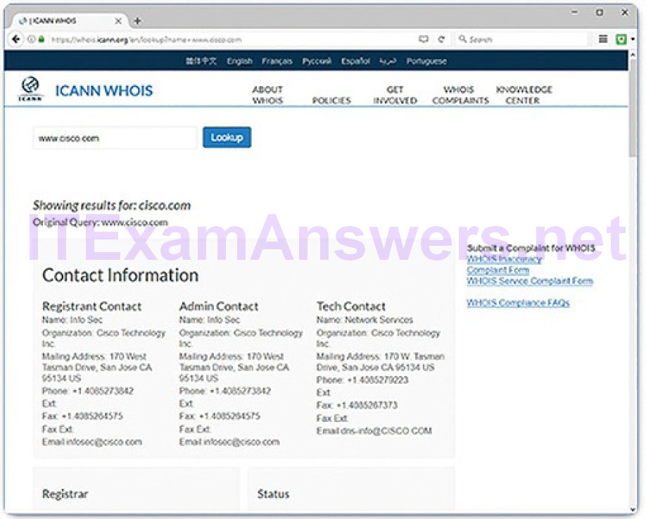
Figure 4-130 The ICANN WHOIS Website
Lab 4.6.2.7: Using Wireshark to Examine a UDP DNS Capture
In this lab, you will communicate with a DNS server by sending a DNS query using the UDP transport protocol. You will use Wireshark to examine the DNS query and response exchanges with the same server.
NAT (4.6.3)
In this topic, you will learn how NAT services enable network functionality.
NAT Overview (4.6.3.1)
There are not enough public IPv4 addresses to assign a unique address to each device connected to the Internet. Networks are commonly implemented using private IPv4 addresses, as defined in RFC 1918. Table 4-5 shows the range of addresses included in RFC 1918. It is very likely that the computer that you use to view this course is assigned a private address.
Table 4-5 Private IPv4 Addresses
| Class | RFC 1918 Internal Address Range | CIDR Prefix |
|---|---|---|
| A | 10.0.0.0 to 10.255.255.255 | 10.0.0.0/8 |
| B | 172.16.0.0 to 172.31.255.255 | 172.16.0.0/12 |
| C | 192.168.0.0 to 192.168.255.255 | 192.168.0.0/16 |
These private addresses are used within an organization or site to allow devices to communicate locally. However, because these addresses do not identify any single company or organization, private IPv4 addresses cannot be routed over the Internet. To allow a device with a private IPv4 address to access devices and resources outside of the local network, the private address must first be translated to a public address, as shown in Figure 4-131.
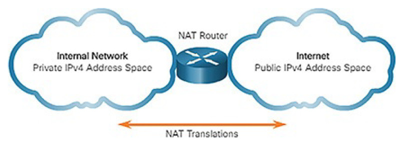
Figure 4-131 Translating Between Private and Public IPv4 Addresses
NAT-Enabled Routers (4.6.3.2)
NAT-enabled routers can be configured with one or more valid public IPv4 addresses. These public addresses are known as the NAT pool. When an internal device sends traffic out of the network, the NAT-enabled router translates the internal IPv4 address of the device to a public address from the NAT pool. Tooutside devices, all traffic entering and exiting the network appears to have a public IPv4 address from the provided pool of addresses.
A NAT router typically operates at the border of a stub network. A stub network is a network that has a single connection to its neighboring network, one way in and one way out of the network. In the example in Figure 4-132, R2 is a border router. As seen from the ISP, R2 forms a stub network.
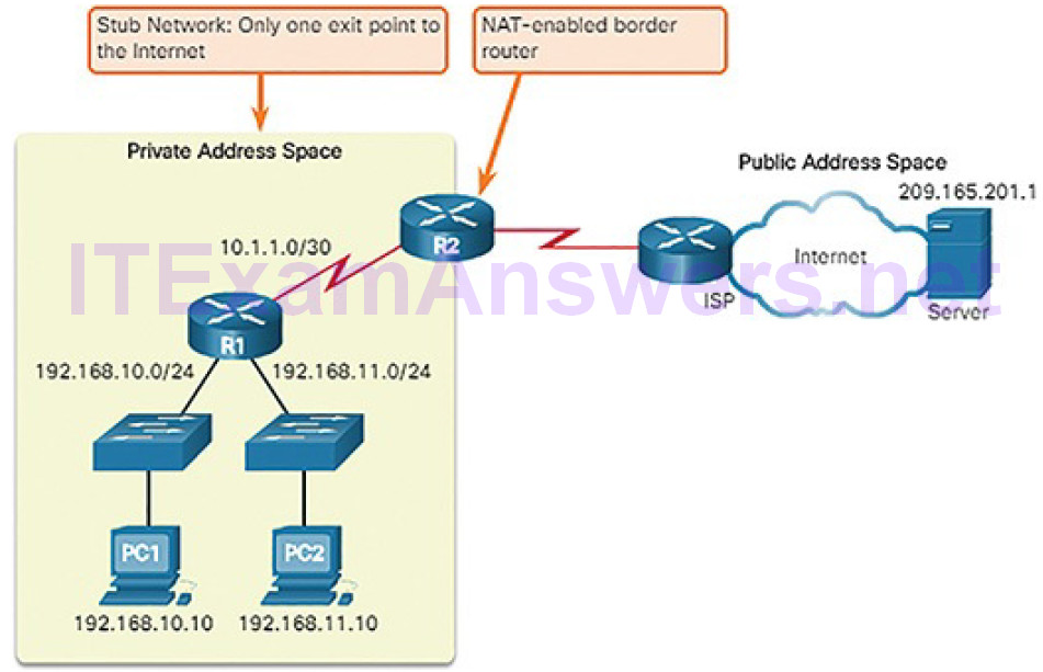
Figure 4-132 NAT Border
When a device inside the stub network wants to communicate with a device outside of its network, the packet is forwarded to the border router. The border router performs the NAT process, translating the internal private address of the device to a public, outside, routable address.
Note
The connection to the ISP may use a private address or a public address that is shared among customers. For the purposes of this chapter, a public address is shown.
Port Address Translation (4.6.3.3)
NAT can be implemented as one-to-one static mappings of private addresses to public addresses, or many internal addresses can be mapped to a single public address. This is known as Port Address Translation (PAT). PAT is quite commonly used in home networks when an ISP provides a single public IP address to the home router. In most homes, multiple devices will require Internet access. PAT allows all of the network devices within the home network to share the single IP address that is provided by the ISP. In larger networks, PAT can be used to map many internal addresses to several public addresses as well.
With PAT, multiple addresses can be mapped to one or to a few addresses, because each private address is also tracked by a port number. When a device initiates a TCP/IP session, it generates a TCP or UDP source port value or a specially assigned query ID for ICMP, to uniquely identify the session. When the NAT router receives a packet from the client, it uses its source port number to uniquely identify the specific NAT translation. The PAT process also validates that the incoming packets were requested, thus adding a degree of security to the session.
Figure 4-133 illustrates the PAT process. PAT adds unique source port numbers to the inside global address to distinguish between translations.
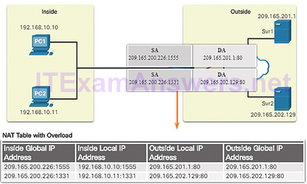
Figure 4-133 PAT Process
As R2 processes each packet, it uses a port number (1331 and 1555, in this example) to identify the device from which the packet originated. The source address (SA) is the inside local address with the TCP/IP assigned port number added. The destination address (DA) is the outside local address with the service port number added. In this example, the service port is 80, which is HTTP.
For the source address, R2 translates the private address (known as an inside local address) to an outside global public address with the port number added. The destination address is not changed, but is now referred to as the outside global IPv4 address. When the web server replies, the path is reversed.
NAT/PAT can complicate cyber-operations because it can hide addressing information in the log files created by network security and monitoring devices.
File Transfer and Sharing Services (4.6.4)
In this topic, you will learn how file transfer services enable network functionality.
FTP and TFTP (4.6.4.1)
FTP and TFTP are two commonly used file transfer protocols.
File Transfer Protocol (FTP)
FTP is another commonly used application layer protocol. FTP was developed to allow for data transfers between a client and a server. An FTP client is an application that runs on a computer that is used to push and pull data from an FTP server.
As Figure 4-134 illustrates, to successfully transfer data, FTP requires two connections between the client and the server, one for commands and replies, the other for the actual file transfer:
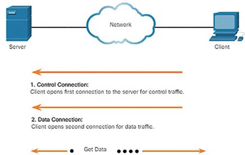
Figure 4-134 FTP Process
1. The client establishes the first connection to the server for control traffic using TCP port 21, consisting of client commands and server replies.
2. The client establishes the second connection to the server for the actual data transfer using TCP port 20. This connection is created every time there is data to be transferred.
The data transfer can happen in either direction. The client can download (pull) data from the server, or the client can upload (push) data to the server.
FTP was not designed to be a secure application layer protocol. For this reason, SSH File Transfer Protocol, which is a secure form of FTP that uses the Secure Shell protocol to provide a secure channel, is the preferred file transfer implementation.
Trivial File Transfer Protocol (TFTP)
TFTP is a simplified file transfer protocol that uses the well-known UDP port number 69. It lacks many of the features of FTP, such as the file management operations of listing, deleting, or renaming files. Because of its simplicity, TFTP has a very low network overhead and is popular for non-critical file transfer applications. It is fundamentally insecure, however, because it has no login or access control features. For this reason, TFTP needs to implemented carefully, and only when absolutely necessary.
SMB (4.6.4.2)
The Server Message Block (SMB) is a client/server file sharing protocol that describes the structure of shared network resources, such as directories, files, printers, and serial ports, as shown in Figure 4-135. It is a request-response protocol. All SMB messages share a common format. This format uses a fixed-sized header, followed by a variable-sized parameter and data component.
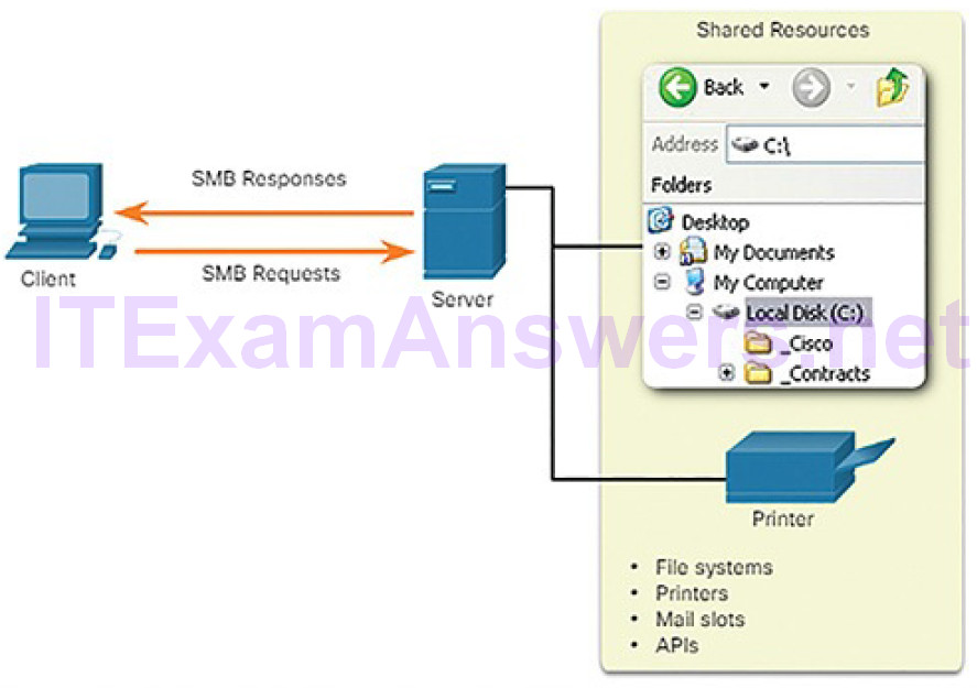
Figure 4-135 SMB Protocol
SMB messages can start, authenticate, and terminate sessions, control file and printer access, and allow an application to send or receive messages to or from another device.
SMB file sharing and print services have become the mainstay of Microsoft networking, as shown in Figure 4-136.
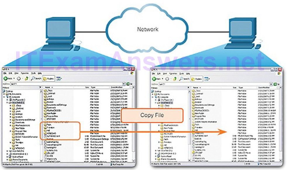
Figure 4-136 SMB File Sharing
Lab 4.6.4.3: Using Wireshark to Examine TCP and UDP Captures
In this lab, you will complete the following objectives:
- Identify TCP header fields and operation using a Wireshark FTP session capture
- Identify UDP header fields and operation using a Wireshark TFTP session capture
Email (4.6.5)
In this topic, you will learn how email services enable network functionality.
Email Overview (4.6.5.1)
Email is an essential network application. To run on a computer or other end device, it requires several applications and services, as shown in Figure 4-137.
Email is a store-and-forward method of sending, storing, and retrieving electronic messages across a network. Email messages are stored in databases onmail servers.
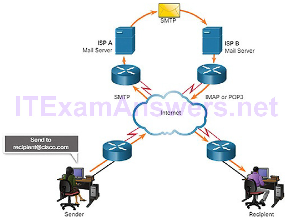
Figure 4-137 Example of the Email Process
Email clients communicate with mail servers to send and receive email. Mail servers communicate with other mail servers to transport messages from one domain to another. An email client does not communicate directly with another email client when sending email. Instead, both clients rely on the mail server to transport messages.
Email supports three separate protocols for operation: Simple Mail Transfer Protocol (SMTP), Post Office Protocol version 3 (POP3), and Internet Message Access Protocol (IMAP). The application layer process that sends mail uses SMTP. A client retrieves email, however, using one of the two application layer protocols: POP3 or IMAP.
SMTP (4.6.5.2)
SMTP message formats require a message header and a message body. While the message body can contain any amount of text, the message header must have aproperly formatted recipient email address and a sender address.
When a client sends email, the client SMTP process connects with a server SMTP process on well-known port 25. After the connection is made, the client attempts to send the email to the server across the connection. When the server receives the message, it either places the message in a local account, if the recipient is local, or forwards the message to another mail server for delivery, as
shown in Figure 4-138.
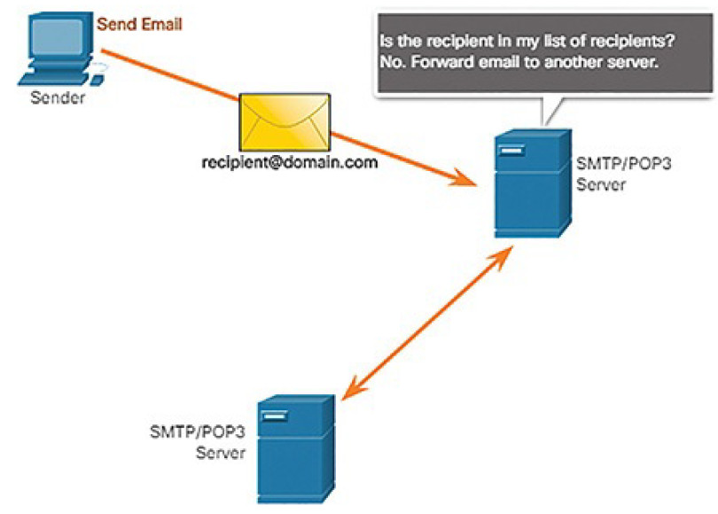
Figure 4-138 SMTP Process
The destination email server may not be online or may be busy when email messages are sent. Therefore, SMTP spools messages to be sent at a later time. Periodically, the server checks the queue for messages and attempts to send them again. If the message is still not delivered after a predetermined expiration time, it is returned to the sender as undeliverable.
POP3 (4.6.5.3)
POP3 is used by an application to retrieve mail from a mail server. With POP3, mail is downloaded from the server to the client and then deleted on the server, as shown in Figure 4-139.
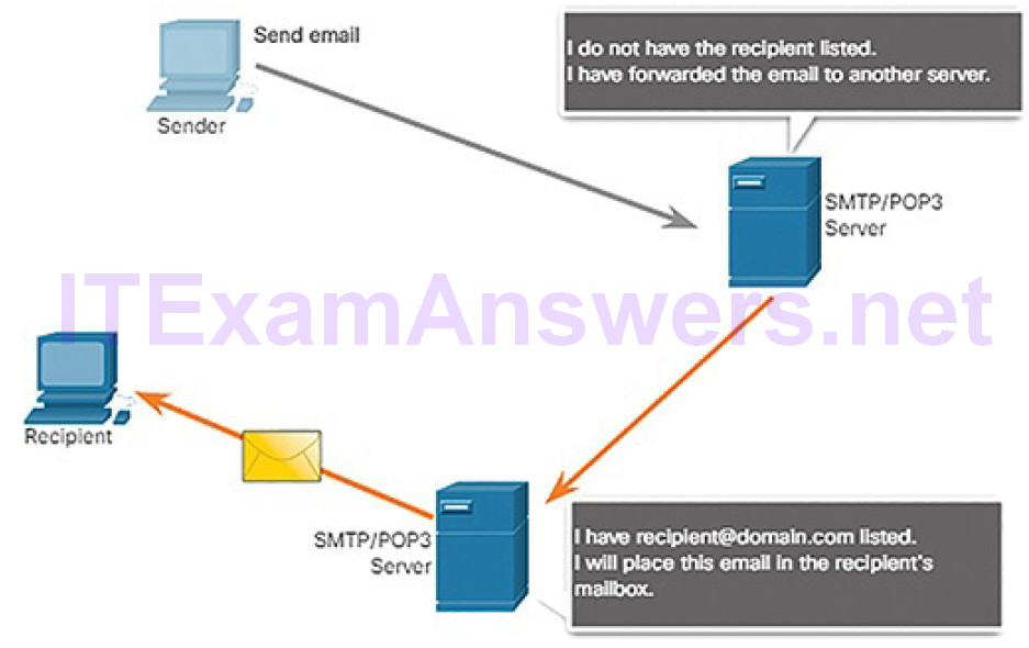
Figure 4-139 POP3 Process
The server starts the POP3 service by passively listening on TCP port 110 for client connection requests. When a client wants to make use of the service, it sends a request to establish a TCP connection with the server. When the connection is established, the POP3 server sends a greeting. The client and POP3 server then exchange commands and responses until the connection is closed or aborted.
With POP3, email messages are downloaded to the client and removed from the server, so there is no centralized location where email messages are kept. Because POP3 does not store messages, it is undesirable for a small business that needs a centralized backup solution.
IMAP (4.6.5.4)
IMAP is another protocol that describes a method to retrieve email messages, as shown in Figure 4-140.
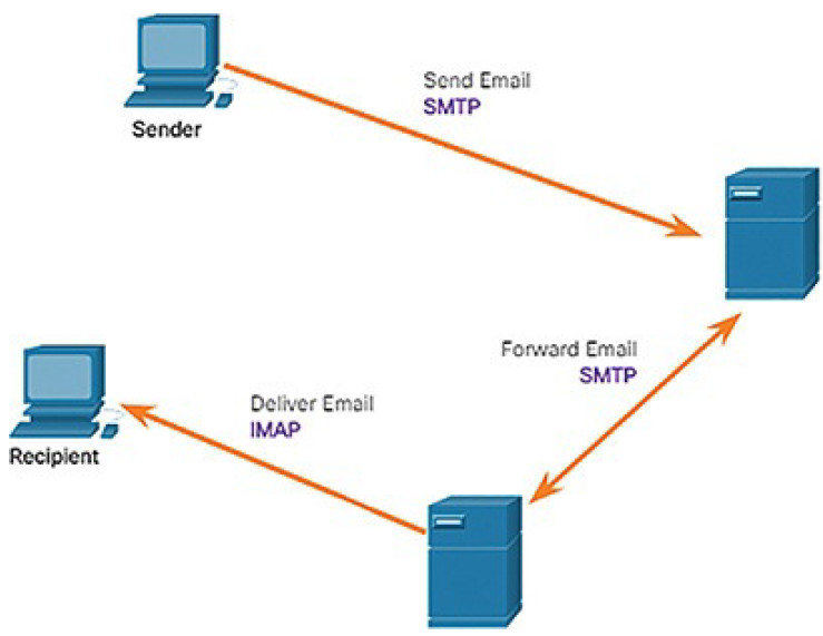
Figure 4-140 IMAP Process
Unlike POP3, when the user connects to an IMAP-capable server, copies of the messages are downloaded to the client application. The original messages are kept on the server until manually deleted. Users view copies of the messages in their email client software.
Users can create a file hierarchy on the server to organize and store mail. That file structure is duplicated on the email client as well. When a user decides to delete a message, the server synchronizes that action and deletes the message from the server.
HTTP (4.6.6)
In this topic, you will learn how HTTP services enable network functionality.
HTTP Overview (4.6.6.1)
To better understand how the web browser and web server interact, we can examine how a web page is opened in a browser. For this example, use the URL http://www.cisco.com, as shown in Figure 4-141.

Figure 4-141 HTTP Example Topology
First, the browser interprets the three parts of the URL:
- http (the protocol or scheme)
- www.cisco.com (the server name)
- index.html (the default home page is requested)
Note
Web servers typically display the home page, index.html, as the default page if no other page is specified. You do not need to enter the full path including the /index.html. If fact, you can simply enter cisco.com. Regardless of whether you enter cisco.com, www.cisco.com, or www.cisco.com/index.html, the web server will display the same home page, index.html.
As shown in Figure 4-142, the browser then checks with a name server to convert www.cisco.com into a numeric IP address, which it uses to connect to the server.
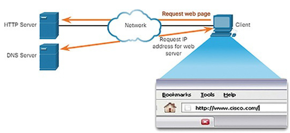
Figure 4-142 HTTP Process: Step 1
Using HTTP requirements, the browser sends a GET request to the server and asks for the index.html file. The server, as shown in Figure 4-143, sends the HTML code for this web page to the browser.
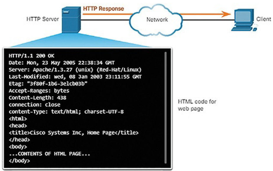
Figure 4-143 HTTP Process: Step 2
Finally, as shown in Figure 4-144, the browser deciphers the HTML code and formats the page for the browser window.
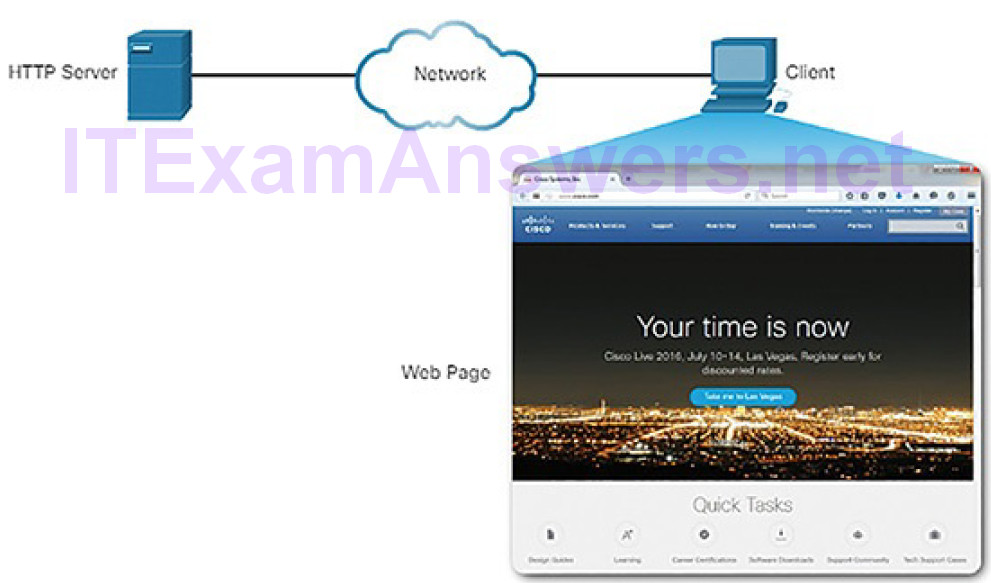
Figure 4-144 HTTP Process: Step 3
The HTTP URL (4.6.6.2)
An HTTP URL can also specify the port on the server that should handle the HTTP methods. In addition, it can specify a query string and fragment. The query string typically contains information that is not handled by the HTTP server process itself, but is instead handled by another process that is running on the server. Query strings are preceded by a “?” character and typically consist of a series of name and value pairs. A fragment is preceded by a “#” character. It refers to a subordinate part of the resource that is requested in the URL. For example, a fragment could refer to a named anchor in an HTML document. The URL will access the document and then move to the part of the document specified by the fragment if a matching named anchor link exists in the document. An HTTP URL that includes these parts is shown in Figure 4-145.

Figure 4-145 Parts of a URL
The HTTP Protocol (4.6.6.3)
HTTP is a request/response protocol that uses TCP port 80, although other ports can be used. When a client, typically a web browser, sends a request to a web server, it will use one of five methods that are specified by the HTTP protocol:
- GET: A client request for data. A client (web browser) sends the GET message to the web server to request HTML pages, as shown in Figure 4- 146.
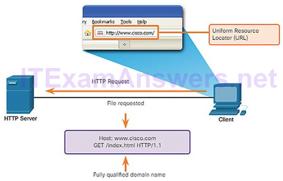
Figure 4-146 HTTP Using GET
- POST: Submits data to be processed by a resource.
- PUT: Uploads resources or content to the web server such as an image.
- DELETE: Deletes the resource specified.
- OPTIONS: Returns the HTTP methods that the server supports.
- CONNECT: Requests that an HTTP proxy server forward the HTTP TCP session to the desired destination.
Although HTTP is remarkably flexible, it is not a secure protocol. The request messages send information to the server in plaintext that can be intercepted and read. The server responses, typically HTML pages, are also unencrypted.
Securing HTTP
For secure communication across the Internet, the HTTP Secure (HTTPS) protocol is used. HTTPS uses TCP port 443. HTTPS uses authentication and encryption to secure data as it travels between the client and server. HTTPS uses the same client request–server response process as HTTP, but the data stream is encrypted with Secure Sockets Layer (SSL), or Transport Layer Security (TLS), before being transported across the network. Although SSL is the predecessor to TLS, both protocols are often referred to as SSL.
Much confidential information, such as passwords, credit card information, and medical information, is transmitted over the Internet using HTTPS.
HTTP Status Codes (4.6.6.4)
The HTTP server responses are identified with various status codes that inform the host application of the outcome of client requests to the server. The codes are organized into five groups. The codes are numeric, with the first number in the code indicating the type of message. The five status code groups are:
- 1xx: Informational
- 2xx: Success
- 3xx: Redirection
- 4xx: Client Error
- 5xx: Server Error
An explanation of some common status codes is shown in Table 4-6.
Table 4-6 Some Common HTTP Status Codes
| CodeStatus | Meaning | |
| 1xx – Informational | ||
| 100 | Continue | The client should continue with request. Server has verified thatthe request can be fulfilled. |
| 2xx – Success | ||
| 200 | OK | The request completed successfully. |
| 202 | Accepted | The request has been accepted for processing, but processing is not completed. |
| 4xx – Client Error | ||
| 403 | Forbidden | The request is understood by the server, but the resource will not be fulfilled, possibly because the requester is not authorized to view the resource. |
| 404 | Not Found | The server cannot find the requested resource. |
Lab 4.6.6.5: Using Wireshark to Examine HTTP and HTTPS Traffic
In this lab, you will complete the following objectives:
- Capture and view HTTP traffic
- Capture and view HTTPS traffic
Summary (4.7)
In this chapter, you learned the basic operation of network protocols and services. Networks come in all sizes, from small, home office networks to the Internet. Protocols are the rules for how traffic is sent across networks. Networking engineers use two models to understand and communicate the operation of protocols: the OSI model and the TCP/IP model. Regardless of the model used, the process of encapsulation describes how data is formatted for transmission across the network so that the destination can receive and de-encapsulate the data.
Ethernet operates at Layer 2 of the OSI model. Ethernet is responsible for encapsulating the upper layer data in a frame, which includes source anddestination MAC addresses. MAC addresses are used on the LAN to locate either the destination or the default gateway.
IP operates at Layer 3 of the OSI model. IP comes in two versions: IPv4 and IPv6. Although IPv4 is being replaced by IPv6, IPv4 is still prevalent on today’s networks. IPv4 uses a 32-bit address space represented in dotted-decimal format, such as 192.168.1.1. IPv6 uses a 128-bit address space represented in hexadecimal format. In IPv6, you can omit leading zeros in each hextet and omit one “all zeros” segment, such as 2001:0DB8:0000:1111:0000:0000:0000:0200 represented as 2001:DB8:0:1111::200.
ICMP is used primarily for testing end-to-end connectivity from source to destination. ICMP for IPv4 is different than ICMP for IPv6. ICMP for IPv6 includes router and neighbor solicitations, router and neighbor advertisements, and duplicate address detection. The ping and traceroute utilities both use a feature of ICMP. Ping is used to test connectivity between two hosts but does not provide information about the details of devices between the hosts. Traceroute (tracert) is a utility that generates a list of hops that were successfully reached along the path.
ARP operates between Layer 2 and Layer 3, mapping MAC addresses to IP addresses. Before a host can send traffic to a remote network, it must know the MAC address for the default gateway. The host already knows the IP address for the default gateway. For example, a host with an IP address 192.168.1.10 might have a default gateway configured of 192.168.1.1. The host uses an ARP request to ask “Who is 192.168.1.1?” The default gateway will reply with its own MAC address. At that point, the host has mapped the IP address to the default gateway’s MAC address and can now construct the frame to send data to a remote network.
The transport layer is responsible for separating the data from the application layer into segments that can be sent down to the network layer. TCP is the transport layer protocol used when all the data must arrive at the destination in the correct order. UDP is the transport layer protocol used when the application can tolerate some data loss during transmission.
At the application layer, there are several important network services that the cybersecurity analysts should be aware of:
- DHCP: This automates the assignment of IPv4 addresses, subnet masks, gateways, and other IPv4 networking parameters.
- DNS: This provides a reliable means of managing and providing domainnames and their associated IP addresses.
- NAT: This translates between private and public IPv4 addresses.
- File Transfer: Applications such as FTP, TFTP, and SMB can be used to transfer files from one host to another.
- Email: This requires several applications and services including POP3, IMAP, and SMTP.
- HTTP: This protocol is used to send and receive web pages.
Practice
The following activities provide practice with the topics introduced in this chapter. The Labs are available in the companion CCNA Cybersecurity Operations Lab Manual (ISBN: 9781587134388).
Labs
Lab 4.1.1.7: Tracing a Route
Lab 4.1.2.10: Introduction to Wireshark
Lab 4.4.2.8: Using Wireshark to Examine Ethernet Frames
Lab 4.5.2.4: Using Wireshark to Observe the TCP 3-Way Handshake
Lab 4.5.2.10: Exploring Nmap
Lab 4.6.2.7: Using Wireshark to Examine a UDP DNS Capture
Lab 4.6.4.3: Using Wireshark to Examine TCP and UDP Captures
Lab 4.6.6.5: Using Wireshark to Examine HTTP and HTTPS Traffic
