Objectives
Upon completion of this chapter, you will be able to answer the following questions:
- How do network devices enable network communication?
- How do wireless devices enable network communication?
- How are specialized devices used to enhance network security?
- How do network services enhance network security?
- How are network designs represented by interconnected symbols?
Key Terms
This chapter uses the following key terms. You can find the definitions in the Glossary.
intermediary device
routers
path determination
packet forwarding
static routes
dynamic routing protocol
CSMA/CD
content addressable memory (CAM)
virtual LANs (VLANs)
Spanning Tree Protocol (STP)
multilayer switches
routed port
switch virtual interface (SVI)
wireless LANs (WLANs)
wireless access point (AP)
CSMA/CA
service set identifier (SSID)
Wireless LAN Controller (WLC)
lightweight APs (LWAPs)
packet filtering (stateless) firewall
stateful firewall
application gateway firewall (proxy firewall)
intrusion prevention systems (IPS)
host-based IPS (HIPS)
access control list (ACL)
Simple Network Management Protocol (SNMP)
NetFlow
packet analyzer
port mirroring
syslog
Network Time Protocol (NTP)
Terminal Access Controller Access-Control System Plus (TACACS+)
Remote Authentication Dial-In User Service (RADIUS)
virtual private network (VPN)
Generic Routing Encapsulation (GRE)
physical topology
logical topology
access layer
distribution layer
core layer
demilitarized zone (DMZ)
zone-based policy firewalls (ZPFs)
Introduction (5.0)
The network infrastructure defines the way in which devices are connected together to achieve end-to-end communications. Just as there are many sizes of networks, there are also many ways to build an infrastructure. However, there are some standard designs that the network industry recommends to achieve networks that are available and secure.
This chapter covers the basic operation of network infrastructures, including wired and wireless networks, network security, and network designs.
Network Communication Devices (5.1)
In this section, you will learn how network devices enable wired and wireless network communication.
Network Devices (5.1.1)
In this topic, you will learn how network devices enable network communication.
End Devices (5.1.1.1)
End devices include computers, laptops, servers, printers, smart devices, and mobile devices. Individual end devices are connected to the network by intermediary devices. Intermediary devices not only connect the individual end devices to the network but also connect multiple individual networks to form an internetwork. These intermediary devices provide connectivity and ensure that data flows across the network. In Figure 5-1, a packet moves from an end device through intermediary devices to another end device.
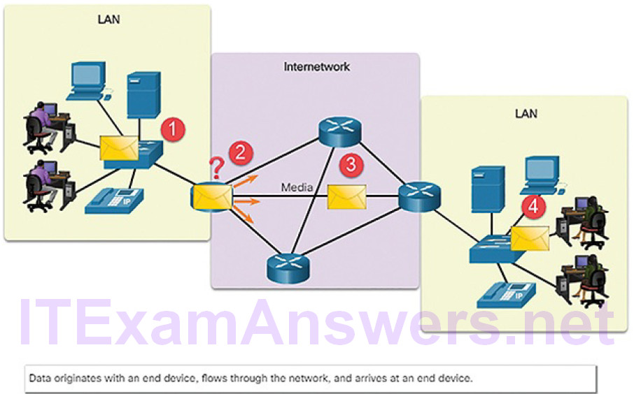
Figure 5-1 Data Flowing Through the Internetwork
Intermediary devices use the destination end device address, in conjunction with information about the network interconnections, to determine the path that messages should take through the network. Examples of the more common intermediary devices are shown in Figure 5-2.

Figure 5-2 Intermediary Network Devices
Intermediary network devices perform some or all of these functions:
- Regenerate and retransmit data signals
- Maintain information about what pathways exist through the network and internetwork
- Notify other devices of errors and communication failures
- Direct data along alternate pathways when there is a link failure
- Classify and direct messages according to priorities
- Permit or deny the flow of data, based on security settings
Video Tutorial 5.1.1.2: End Devices
Refer to the online course to view this video.
Routers (5.1.1.3)
Routers are devices that operate at the OSI network layer. They use the process of routing to forward data packets between networks, or subnetworks, as shown in Figure 5-3.
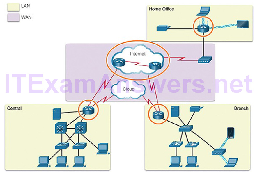
Figure 5-3 The Router Connection
The routing process uses network routing tables, protocols, and algorithms to determine the most efficient path for forwarding an IP packet. Routers gather routing information and update other routers about changes in the network. Routers increase the scalability of networks by segmenting broadcast domains.
Routers have two primary functions: path determination and packet forwarding. To perform path determination, each router builds and maintains a routing table, which is a database of known networks and how to reach them. The routing table can be built manually and contain static routes or can be built using a dynamic routing protocol.
Packet forwarding is accomplished by using a switching function. Switching is the process used by a router to accept a packet on one interface and forward it out of another interface. A primary responsibility of the switching function is to encapsulate packets in the appropriate data link frame type for the outgoing data link. Figure 5-4 shows R1 receiving a packet on one network and preparing to forward the packet out of another network toward the destination network.
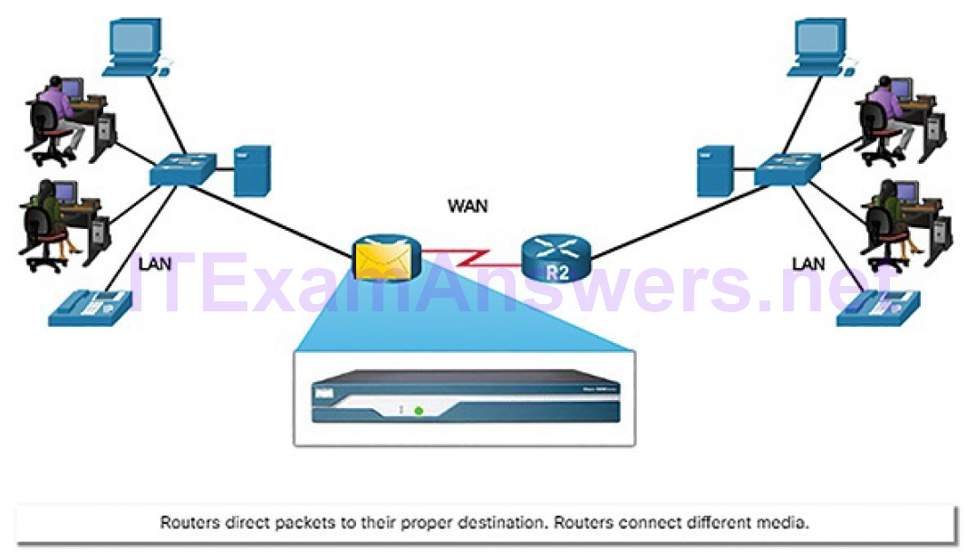
Figure 5-4 Routers Connect
After the router has determined the exit interface using the path determination function, the router must encapsulate the packet into the data link frame of the outgoing interface.
What does a router do with a packet received from one network and destined for another network? The router performs the following three major steps:
- It de-encapsulates the Layer 2 frame header and trailer to expose the Layer 3 packet.
- It examines the destination IP address of the IP packet to find the best path in the routing table.
- If the router finds a path to the destination, it encapsulates the Layer 3 packet into a new Layer 2 frame and forwards that frame out the exit interface.
As shown in Figure 5-5, devices have Layer 3 IPv4 addresses, while Ethernet interfaces have Layer 2 data link addresses.
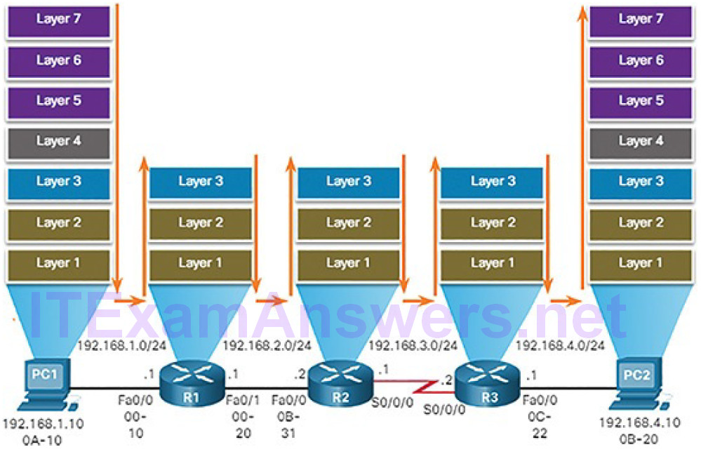
Figure 5-5 Encapsulating and De-Encapsulating Packets
The MAC addresses are shortened to simplify the illustration. For example, PC1 is configured with IPv4 address 192.168.1.10 and an example MAC address of 0A-10. As a packet travels from the source device to the final destination device, the Layer 3 IP addresses do not change. This is because the Layer 3 PDU does not change. However, the Layer 2 data link addresses change at every router on the path to the destination, as the packet is de-encapsulated and re-encapsulated in a new Layer 2 frame.
Activity 5.1.1.4: Match Layer 2 and Layer 3 Addressing
Refer to the online course to complete this Activity.
Router Operation (5.1.1.5)
To increase scalability, networks can be divided into subnetworks, which are called subnets. Subnets create the network segments which support end devices and create a hierarchical structure. A primary function of a router is to determine the best path to use to send packets to each subnet. To determine the best path,the router searches its routing table for a network address that matches the destination IP address of the packet.
The routing table search results in one of three path determinations:
- Directly connected network: If the destination IP address of the packet belongs to a device on a network that is directly connected to one of the interfaces of the router, that packet is forwarded directly to the destination device. This means that the destination IP address of the packet is a host address on the same network as the interface of the router.
- Remote network: If the destination IP address of the packet belongs to a remote network, then the packet is forwarded to another router. Remote networks can only be reached by forwarding packets to another router.
- No route determined: If the destination IP address of the packet does not belong to either a connected or remote network, then the router determines if there is a Gateway of Last Resort available. A Gateway of Last Resort is set when a default route is configured or learned on a router. If there is a default route, the packet is forwarded to the Gateway of Last Resort. If the router does not have a default route, then the packet is discarded.
The logic flowchart in Figure 5-6 illustrates the router packet forwarding decision process.
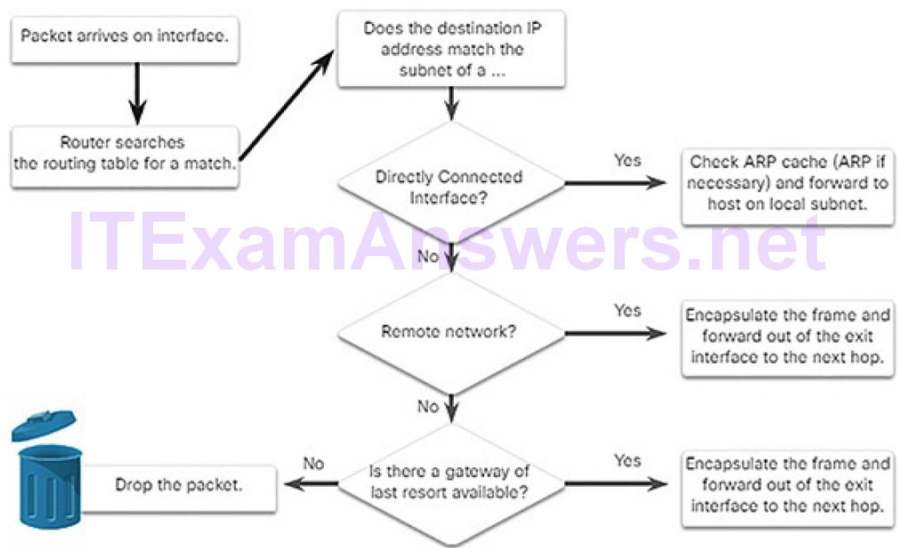
Figure 5-6 Packet Forwarding Decision Process
Because routers do not forward Ethernet broadcast frames, they separate a network into separate broadcast domains. This keeps broadcast traffic isolated to a given network attached to a router interface.
In Figure 5-7, PC1 is sending a packet to PC2.
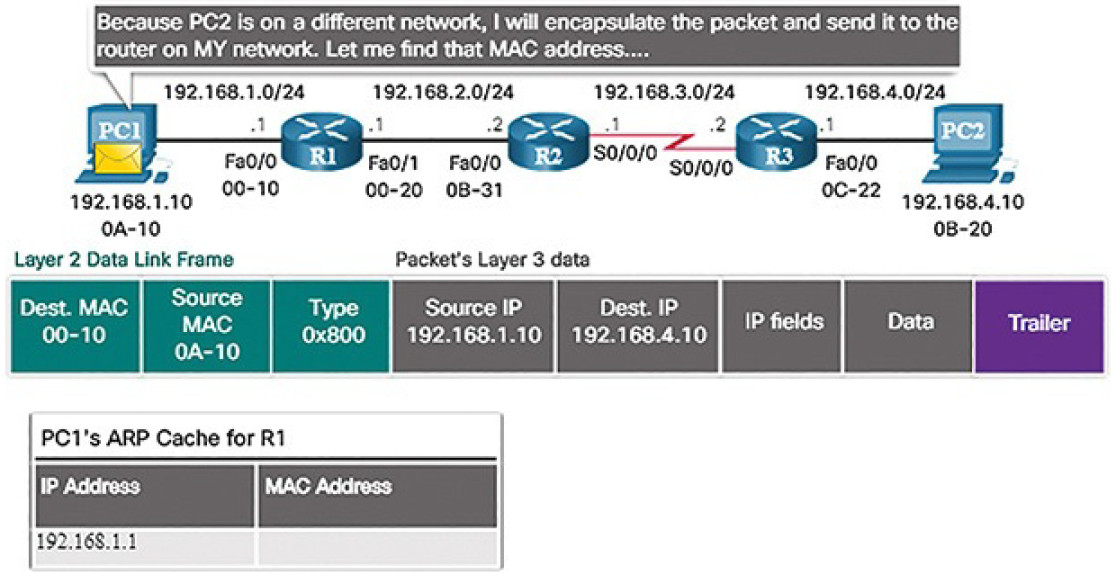
Figure 5-7 PC1 Builds a Packet to Send to PC2
PC1 must determine if the destination IPv4 address is on the same network. PC1 determines its own subnet by doing an AND operation on its own IPv4 address and subnet mask. This produces the network address to which PC1 belongs.
Next, PC1 does this same AND operation using the packet destination IPv4 address and the PC1 subnet mask. The result tells PC1 that PC2 is not on the same network as PC1. Therefore, PC1 builds a packet to send to its default gateway, R1.
Routing Information (5.1.1.6)
The routing table of a router stores the following information:
- Directly connected routes: These routes come from the active router interfaces. Routers add a directly connected route when an interface is configured with an IP address and is activated.
- Remote routes: These are remote networks connected to other routers. Routes to these networks can either be statically configured or dynamically learned through dynamic routing protocols.
Specifically, a routing table is a data file in RAM that is used to store route information about directly connected and remote networks. The routing table contains network or next-hop associations. These associations tell a router that a particular destination can be optimally reached by sending the packet to a specific router that represents the next hop on the way to the final destination. The next-hop association can also be the outgoing or exit interface to the next destination.
Figure 5-8 identifies the directly connected networks and remote networks of router R1.
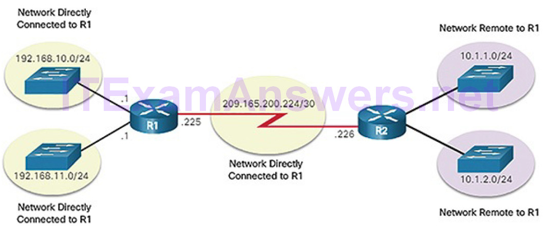
Figure 5-8 Directly Connected and Remote Network Routes
The destination network entries in the routing table can be added in several ways:
- Local route interfaces: These are added when an interface is configured and active. This entry is only displayed in IOS 15 or newer for IPv4 routes, and all IOS releases for IPv6 routes.
- Directly connected interfaces: These are added to the routing table whenan interface is configured and active.
- Static routes: These are added when a route is manually configured and the exit interface is active.
- Dynamic routing protocol: This is added when routing protocols that dynamically learn about the network, such as EIGRP or OSPF, are implemented and networks are identified.
Dynamic routing protocols exchange network reachability information between routers and dynamically adapt to network changes. Each routing protocol uses routing algorithms to determine the best paths between different segments in the network, and updates routing tables with these paths.
Dynamic routing protocols have been used in networks since the late 1980s. One of the first routing protocols was the Routing Information Protocol (RIP). RIPv1 was released in 1988. As networks evolved and became more complex, new routing protocols emerged. The RIP protocol was updated to RIPv2 to accommodate growth in the network environment. However, RIPv2 still does not scale to the larger network implementations of today. To address the needs of larger networks, two advanced routing protocols were developed: Open Shortest Path First (OSPF) and Intermediate System-to-Intermediate System (IS-IS). Cisco developed the Interior Gateway Routing Protocol (IGRP) and Enhanced IGRP (EIGRP), which also scales well in larger network implementations.
Additionally, there was the need to connect different internetworks and provide routing between them. The Border Gateway Protocol (BGP) is now used between Internet service providers (ISPs). BGP is also used between ISPs and their larger private clients to exchange routing information.
Table 5-1 classifies the protocols. Routers configured with these protocols will periodically send messages to other routers. As a cybersecurity analyst, you will see these messages in various logs and packet captures.
Table 5-1 Routing Protocol Classification
| Interior Gateway Protocols | Exterior Gateway Protocols | ||
| Distance Vector | Link-State | Path Vector | |
| IPv4 | RIPv2EIGRP | OSPFv2IS-IS | BGP-4 |
| IPv6 | RIPngEIGRP for IPv6 | OSPFv3IS-IS for IPv6 | BGP-MP |
Video Tutorial 5.1.1.7: Static and Dynamic Routing
Refer to the online course to view this video.
Hubs, Bridges, LAN Switches (5.1.1.8)
The topology icons for hubs, bridges, and LAN switches are shown in Figure 5-9.
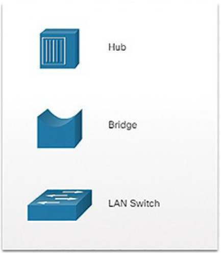
Figure 5-9 LAN Devices
An Ethernet hub acts as a multiport repeater that receives an incoming electrical signal (data) on a port. It then immediately forwards a regenerated signal out all other ports. Hubs use physical layer processing to forward data. They do not look at the source and destination MAC address of the Ethernet frame. Hubs connect the network into a star topology with the hub as the central connection point. When two or more end devices connected to a hub send data at the same time, an electrical collision takes place, corrupting the signals. All devices connected to a hub belong to the same collision domain. Only one device can transmit traffic at any given time on a collision domain. If a collision does occur, end devices use CSMA/CD logic to avoid transmission until the network is clearof traffic.
Bridges have two interfaces and are connected between hubs to divide the network into multiple collision domains. Each collision domain can have only one sender at a time. Collisions are isolated by the bridge to a single segment and do not impact devices on other segments. Just like a switch, a bridge makes forwarding decisions based on Ethernet MAC addresses.
LAN switches are essentially multiport bridges that connect devices into a star topology. Like bridges, switches segment a LAN into separate collision domains, one for each switch port. A switch makes forwarding decisions based on Ethernet MAC addresses. Figure 5-10 shows the Cisco series of 2960-X switches that are commonly used to connect end devices on a LAN.
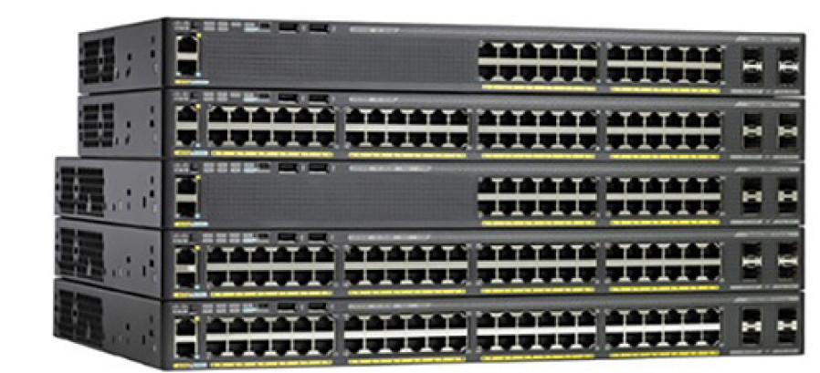
Figure 5-10 Cisco 2960-X Series Switches
Switching Operation (5.1.1.9)
Switches use MAC addresses to direct network communications through the switch, to the appropriate port, and toward the destination. A switch is made up of integrated circuits and the accompanying software that controls the data paths through the switch. For a switch to know which port to use to transmit a frame, it must first learn which devices exist on each port. As the switch learns the relationship of ports to devices, it builds a table called a MAC address table, or content addressable memory (CAM) table. CAM is a special type of memory used in high-speed searching applications.
LAN switches determine how to handle incoming data frames by maintaining the MAC address table. A switch builds its MAC address table by recording the MAC address of each device connected to each of its ports. The switch uses the information in the MAC address table to send frames destined for a specific device out the port which has been assigned to that device.
The following two-step process is performed on every Ethernet frame that enters a switch.
Step 1. Learn: Examining the Source MAC Address
Every frame that enters a switch is checked for new information to learn. The switch does this by examining the frame’s source MAC address and port number where the frame entered the switch. If the source MAC address does not exist, it is added to the table along with the incoming port number, as shown in Figure 5-11. If the source MAC address does exist, the switch updates the refresh timer for that entry. By default, most Ethernet switches keep an entry in the table for 5 minutes.
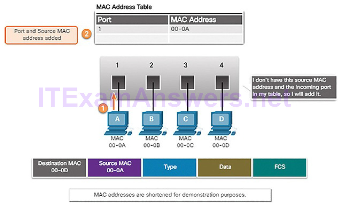
Figure 5-11 Switches Learn by Examining Source MAC Addresses
Note
If the source MAC address does exist in the table but on a different port, the switch treats this as a new entry. The entry is replaced using the same MAC address, but with the more current port number.
Step 2. Forward: Examining the Destination MAC Address
If the destination MAC address is a unicast address, the switch will look for a match between the destination MAC address of the frame and an entry in its MAC address table. If the destination MAC address is in the table, it will forward the frame out the specified port. If the destination MAC address is not in the table, the switch will forward the frame out all ports except the incoming port, as shown in Figure 5-12. This is called an unknown unicast.
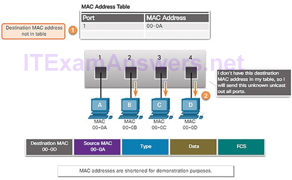
Figure 5-12 Switches Forward by Examining Destination MAC Address
Note
If the destination MAC address is a broadcast or a multicast, the frame is also flooded out all ports except the incoming port.
Video Tutorial 5.1.1.10: MAC Address Tables on Connected Switches
Refer to the online course to view this video.
VLANs (5.1.1.11)
Within a switched internetwork, virtual LANs (VLANs) provide segmentation and organizational flexibility. VLANs provide a way to group devices within a LAN. A group of devices within a VLAN communicate as if they were connected to the same network segment. VLANs are based on logical connections, instead of physical connections.
VLANs allow an administrator to segment networks based on factors such as function, project team, or application, without regard for the physical location of the user or device, as shown in Figure 5-13.
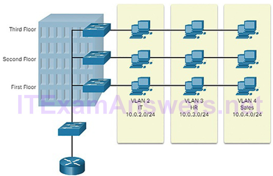
Figure 5-13 Defining VLAN Groups
Devices within a VLAN act as if they are in their own independent network, even if they share a common infrastructure with other VLANs. Any switch portcan belong to a VLAN. Unicast, broadcast, and multicast packets are forwarded and flooded only to end devices within the VLAN where the packets are sourced. Each VLAN is considered a separate logical network. Packets destined for devices that do not belong to the VLAN must be forwarded through a device that supports routing.
A VLAN creates a logical broadcast domain that can span multiple physical LAN segments. VLANs improve network performance by separating large broadcast domains into smaller ones. If a device in one VLAN sends a broadcast Ethernet frame, all devices in the VLAN receive the frame, but devices in other VLANs do not.
VLANs also prevent users on different VLANs from snooping on each other’s traffic. For example, even though HR and Sales are connected to the same switch in Figure 5-13, the switch will not forward traffic between the HR and Sales VLANs. This allows a router or another device to use access control lists (ACLs) to permit or deny the traffic. Access control lists are discussed in more detail later in the chapter. For now, just remember that VLANs can help limit the amount of data visibility on your LANs.
STP (5.1.1.12)
Network redundancy is a key to maintaining network reliability. Multiple physical links between devices provide redundant paths. The network can then continue to operate when a single link or port has failed. Redundant links can also share the traffic load and increase capacity.
Multiple paths need to be managed so that Layer 2 loops are not created. The best paths are chosen, and an alternate path is immediately available should a primary path fail. The Spanning Tree Protocol (STP) is used to maintain one loop-free path in the Layer 2 network, at any time.
Redundancy increases the availability of the network topology by protecting the network from a single point of failure, such as a failed network cable or switch. When physical redundancy is introduced into a design, loops and duplicate frames occur. Loops and duplicate frames have severe consequences for a switched network. STP was developed to address these issues.
STP ensures that there is only one logical path between all destinations on the network by intentionally blocking redundant paths that could cause a loop. A port is considered blocked when user data is prevented from entering or leavingthat port. This does not include bridge protocol data unit (BPDU) frames that are used by STP to prevent loops. Blocking the redundant paths is critical to preventing loops on the network. The physical paths still exist to provide redundancy, but these paths are disabled to prevent the loops from occurring. If the path is ever needed to compensate for a network cable or switch failure, STP recalculates the paths and unblocks the necessary ports to allow the redundant path to become active.
In this example, all switches have STP enabled:
1. PC1 sends a broadcast out onto the network (Figure 5-14).
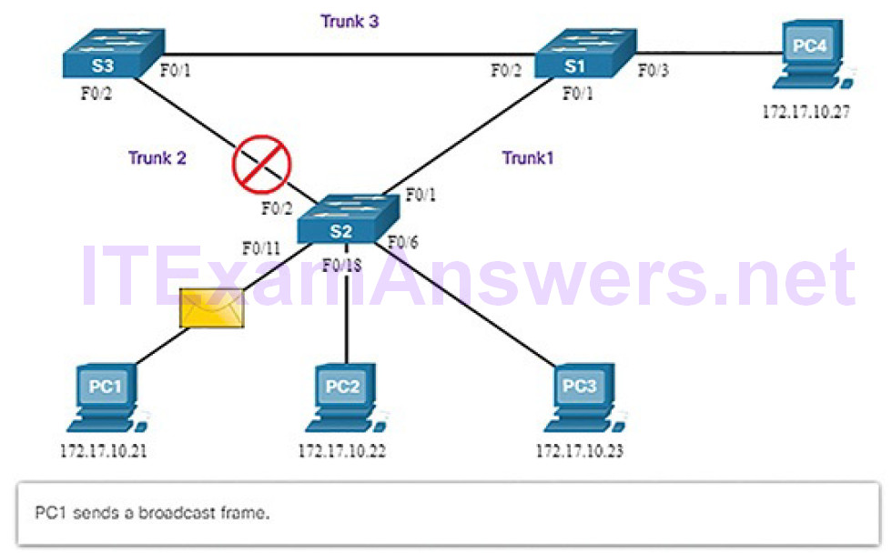
Figure 5-14 Normal STP Operation: PC1 Sends a Broadcast
2. S2 is configured with STP and has set the port for Trunk2 to a blocking state. The blocking state prevents ports from being used to forward user data, which prevents a loop from occurring. S2 forwards a broadcast frame out all switch ports (Figure 5-15), except the originating port from PC1 and the port for Trunk2.
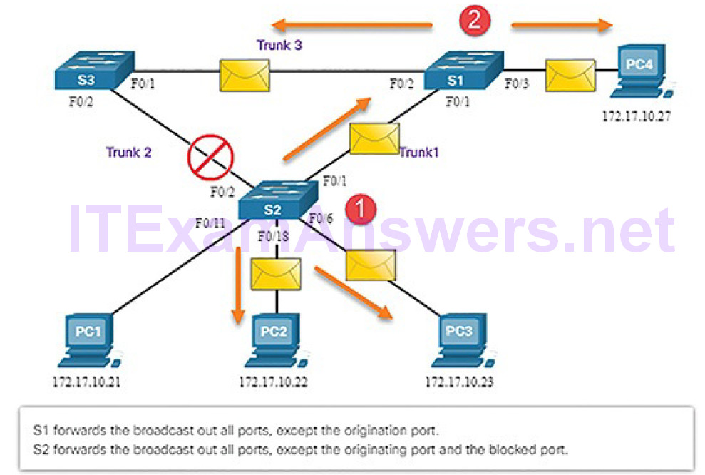
Figure 5-15 Normal STP Operation: S1 and S3 Forward the Broadcast
3. S1 receives the broadcast frame and forwards it out all of its switch ports, where it reaches PC4 and S3. S3 forwards the frame out the port for Trunk2 and S2 drops the frame (Figure 5-16). The Layer 2 loop is prevented.
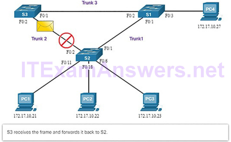
Figure 5-16 Normal STP Operation: S3 Forwards Broadcast to S2
Figures 5-17 through 5-21 illustrate STP recalculation when a failure occurs.
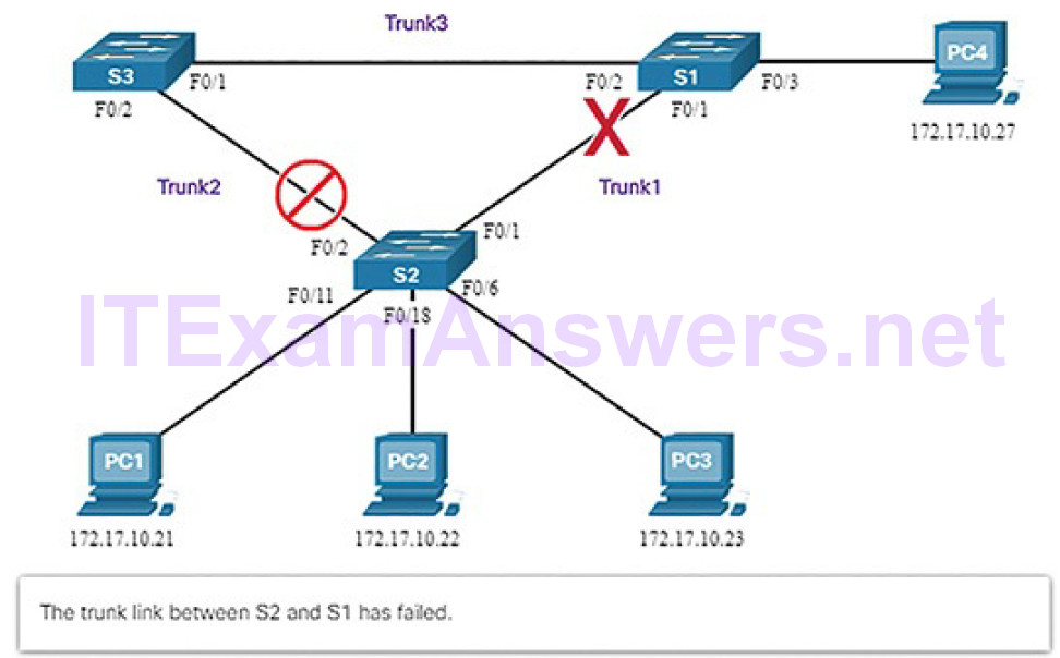
Figure 5-17 STP Detects a Link Failure
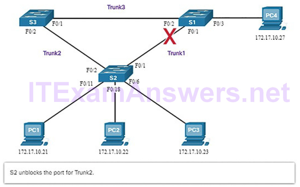
Figure 5-18 STP Unblocks Alternative Link
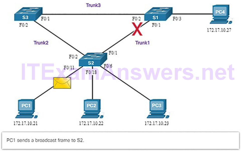
Figure 5-19 STP Compensates for Link Failure: PC1 Sends a Broadcast
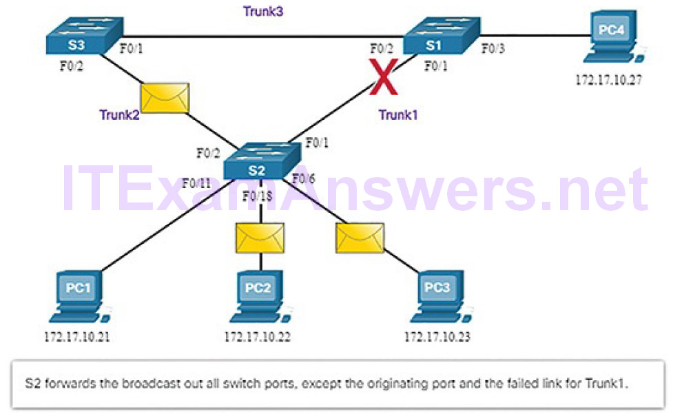
Figure 5-20 STP Compensates for Link Failure: S2 Forwards the Broadcast
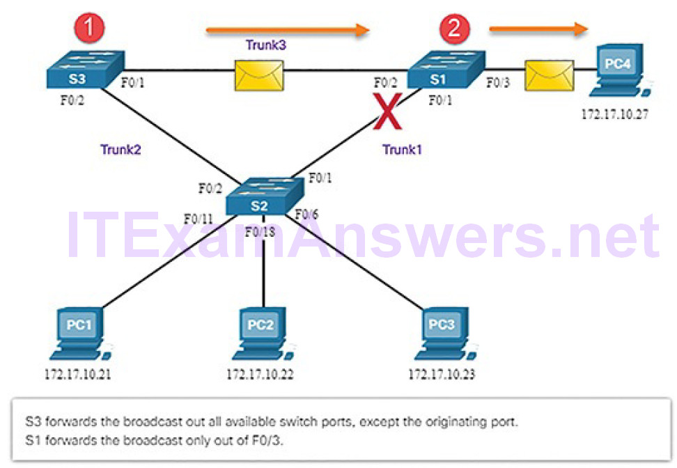
Figure 5-21 STP Compensates for Link Failure: S3 and S1 Forward the Broadcast
STP prevents loops from occurring by configuring a loop-free path through the network using strategically placed “blocking-state” ports. The switches running STP are able to compensate for failures by dynamically unblocking the previously blocked ports and permitting traffic to traverse the alternate paths.
STP generates traffic on the network. It will appear in some packet captures. Wireshark will recognize the traffic and identify the protocol as STP in the capture window.
Multilayer Switching (5.1.1.13)
Multilayer switches (also known as Layer 3 switches) not only perform Layer 2 switching, but also forward frames based on Layer 3 and 4 information. All Cisco Catalyst multilayer switches support the following types of Layer 3 interfaces:
Routed port: A pure Layer 3 interface similar to a physical interface on a Cisco IOS router.
Switch virtual interface (SVI): A virtual VLAN interface for inter-VLAN routing. In other words, SVIs are the virtual-routed VLAN interfaces.
Routed Ports
A routed port is a physical port that acts similarly to an interface on a router (Figure 5-22).
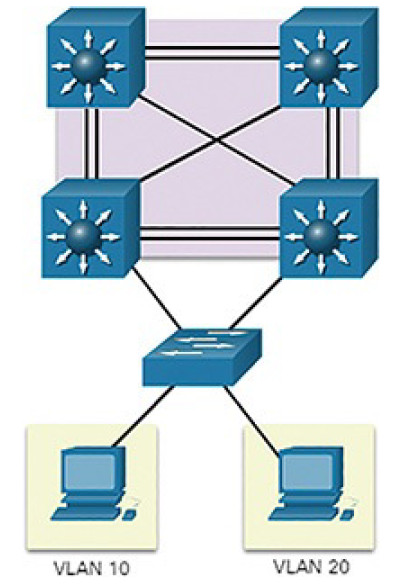
Figure 5-22 Routed Ports
Unlike an access port, a routed port is not associated with a particular VLAN. A routed port behaves like a regular router interface. Also, because Layer 2 functionality has been removed, Layer 2 protocols, such as STP, do not function on a routed interface. However, some protocols, such as LACP and EtherChannel, do function at Layer 3. Unlike Cisco IOS routers, routed ports on a Cisco IOS switch do not support subinterfaces.
Switch Virtual Interfaces
An SVI is a virtual interface that is configured within a multilayer switch, as shown in Figure 5-23.
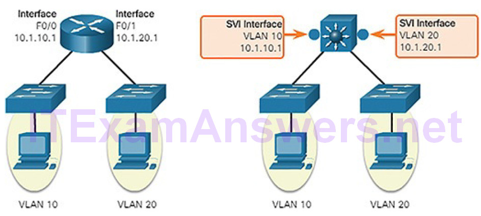
Figure 5-23 Switch Virtual Interface
Unlike the basic Layer 2 switches discussed above, a multilayer switch can have multiple SVIs. An SVI can be created for any VLAN that exists on the switch. An SVI is considered to be virtual because there is no physical port dedicated to the interface. It can perform the same functions for the VLAN as a router interface would, and can be configured in much the same way as a router interface (i.e., IP address, inbound/outbound ACLs, etc.). The SVI for the VLAN provides Layer 3 processing for packets to or from all switch ports associated with that VLAN.
Wireless Communications (5.1.2)
In this topic, you will learn how wireless devices enable network communication.
Video Tutorial 5.1.2.1: Wireless Communications
Refer to the online course to view this video.
Protocols and Features (5.1.2.2)
Wireless LANs (WLANs) use radio frequencies (RF) instead of cables at the physical layer and MAC sublayer of the data link layer. WLANs share a similar origin with Ethernet LANs. The IEEE has adopted the 802 LAN/MAN portfolio of computer network architecture standards. The two dominant 802 workinggroups are 802.3 Ethernet, which defined Ethernet for wired LANs, and 802.11, which defined Ethernet for WLANs. There are important differences between the two, as shown in Table 5-2.
Table 5-2 WLANs Versus LANs
| Characteristic | 802.11 Wireless LAN | 802.3 Ethernet LANs |
| Physical Layer | Radio frequency (RF) | Cable |
| Media Access | Collision Avoidance | Collision Detection |
| Availability | Anyone with a radio NIC in range of an access point | Cable connection required |
| Signal Interference | Yes | Inconsequential |
| Regulation | Additional regulation by country authorities | IEEE standard dictates |
WLANs also differ from wired LANs as follows:
- WLANs connect clients to the network through a wireless access point (AP) or wireless router, instead of an Ethernet switch.
- WLANs connect mobile devices that are often battery powered, as opposed to plugged-in LAN devices. Wireless NICs tend to reduce the battery life of a mobile device.
- WLANs support hosts that contend for access on the RF media (frequency bands). 802.11 prescribes collision avoidance (CSMA/CA) instead of collision detection (CSMA/CD) for media access to proactively avoid collisions within the media.
- WLANs use a different frame format than wired Ethernet LANs. WLANs require additional information in the Layer 2 header of the frame.
- WLANs raise more privacy issues because radio frequencies can reach outside the facility.
All Layer 2 frames consist of a header, payload, and FCS section as shown inFigure 5-24. The 802.11 frame format is similar to the Ethernet frame format, with the exception that it contains additional fields.
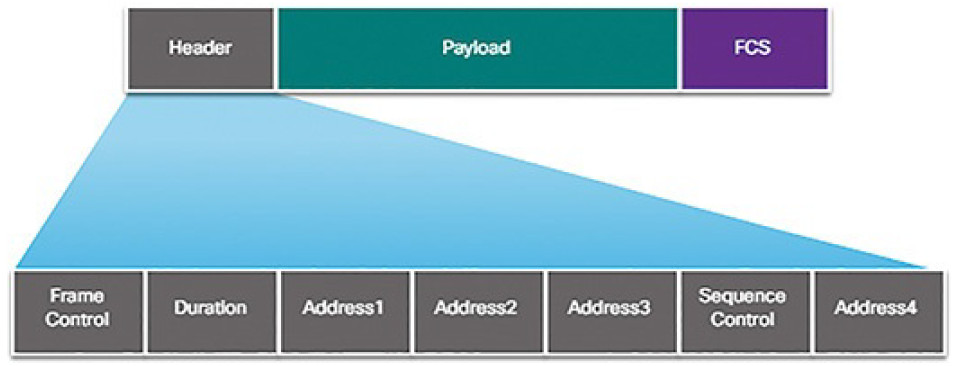
Figure 5-24 Content of Wireless 802.11 Frame Header
As shown in Figure 5-24, all 802.11 wireless frames contain the following fields:
- Frame Control: Identifies the type of wireless frame and contains subfields for Protocol Version, Frame Type, Address Type, Power Management, and Security Settings.
- Duration: Typically used to indicate the remaining time needed to receive the next frame transmission.
- Address1: Usually contains the MAC address of the receiving wireless device or AP.
- Address2: Usually contains the MAC address of the transmitting wireless device or AP.
- Address3: Sometimes contains the MAC address of the destination, such as the router interface (default gateway) to which the AP is attached.
- Sequence Control: Contains the Sequence Number and the Fragment Number subfields. The Sequence Number indicates the sequence number of each frame. The Fragment Number indicates the number of each frame sent of a fragmented frame.
- Address4: Usually empty because it is used only in ad hoc mode.
- Payload: Contains the data for transmission.
- FCS: Frame Check Sequence; used for Layer 2 error control.
Wireless Network Operations (5.1.2.3)
For wireless devices to communicate over a network, they must first associate with an AP or wireless router. An important part of the 802.11 process is discovering a WLAN and subsequently connecting to it.
Management frames are used by wireless devices to complete the following three-stage process, as shown in Figure 5-25:
1. Discover new wireless AP.
2. Authenticate with AP.
3. Associate with AP.
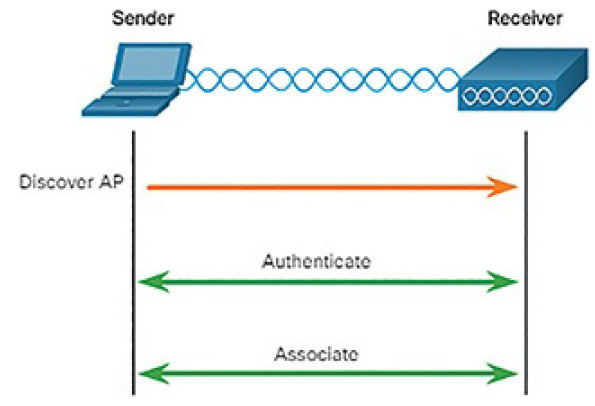
Figure 5-25 802.3 Wireless Association Is a Three-Stage Process
To associate with each other, a wireless client and an AP must agree on specific parameters. Parameters must be configured on the AP, as shown in Figure 5-26, and subsequently on the client to enable the negotiation of these processes.
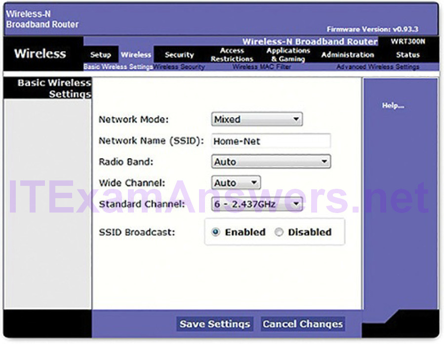
Figure 5-26 Basic Wireless Settings Example
Common configurable wireless parameters include
- Network mode: Refers to the 802.11 WLAN standards. APs and wireless routers can operate in a Mixed mode, as shown in Figure 5-26, which means that they can simultaneously use multiple standards.
- SSID: A service set identifier (SSID) is a unique identifier that wireless clients use to distinguish between multiple wireless networks in the same vicinity. If SSID broadcast is enabled, the SSID name appears in the list of available wireless networks on a client. Depending on the network configuration, several APs on a network can share an SSID. Names are usually 2 to 32 characters long. In Figure 5-26, the SSID is configured as Home-Net and SSID broadcast is enabled.
- Channel settings: Refers to the frequency bands being used to transmit wireless data. Wireless routers and APs can choose the channel setting or it can be set manually if there is interference with another AP or wireless device. In Figure 5-26, the channel is manually set to 6, which is the 2.437 GHz frequency.
- Security mode: Refers to the security parameter settings, such as WEP,WPA, or WPA2. Always enable the highest security level supported. For a home or small office, you would use WPA2 Personal.
- Encryption: WPA2 requires that you choose an encryption. Use AES whenever possible.
- Password: Required from the wireless client to authenticate to the AP. A password is sometimes called the security key. It prevents intruders and other unwanted users from accessing the wireless network.
Wireless devices must discover and connect to an AP or wireless router. Wireless clients connect to the AP using a scanning (probing) process. This process can be passive or active:
- Passive mode: The AP openly advertises its service by periodically sending broadcast beacon frames containing the SSID, supported standards, and security settings. The primary purpose of the beacon is to allow wireless clients to learn which networks and APs are available in a given area, thereby allowing them to choose which network and AP to use.
- Active mode: Wireless clients must know the name of the SSID. The wireless client initiates the process by broadcasting a Probe Request frame on multiple channels. The probe request includes the SSID name and standards supported. Active mode may be required if an AP or wireless router is configured to not broadcast beacon frames.
The 802.11 standard was originally developed with two authentication mechanisms:
- Open authentication: Fundamentally a NULL authentication where the wireless client says “authenticate me” and the AP responds with “yes.” Open authentication provides wireless connectivity to any wireless device and should only be used in situations where security is of no concern.
- Shared key authentication: Technique is based on a key that is pre-shared between the client and the AP.
The Client to AP Association Process (5.1.2.4)
A wireless client goes through a three-stage process to associate with an AP.
After the wireless client has associated with the AP, traffic is able to flow between the client and the AP.
Stage 1: Discovery
In the discovery phase, a wireless client locates the appropriate AP to first associate with. After the client has associated, other APs may be used if the client is roaming through the network.
Figure 5-27 illustrates how passive mode works with the AP broadcasting a beacon frame every so often.
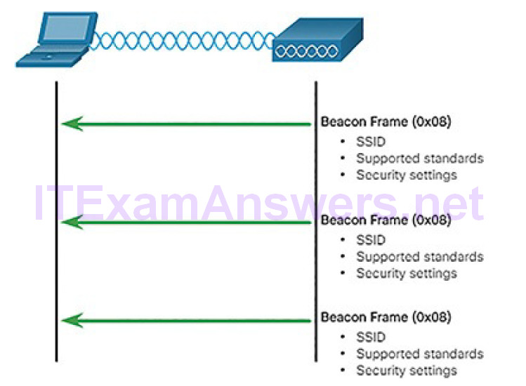
Figure 5-27 Client Devices Listen for an AP
Figure 5-28 illustrates how active mode works with a wireless client broadcasting a probe request for a specific SSID. The AP with that SSID responds with a probe response frame.
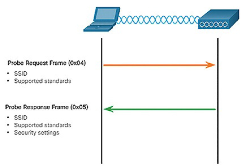
Figure 5-28 Active Mode Request and Response Probes
A wireless client could also send a probe request without an SSID name to discover nearby WLAN networks. APs configured to broadcast beacon frames would respond to the wireless client with a probe response and provide the SSID name. APs with the broadcast SSID feature disabled do not respond.
Stage 2: Authentication
Figure 5-29 provides a simple overview of the authentication process.
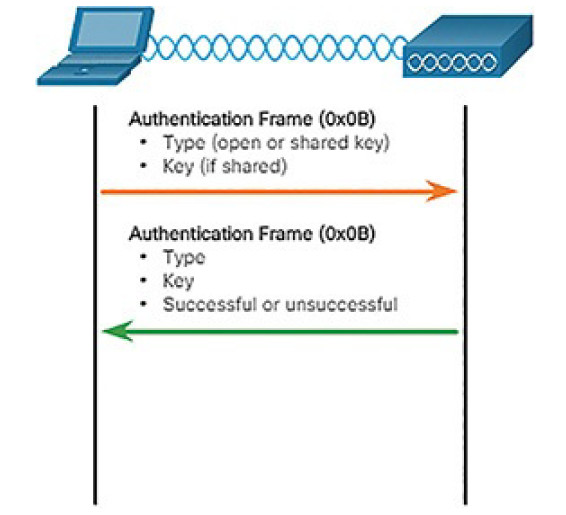
Figure 5-29 Client and AP Authenticate
However, in most shared key authentication installations, the exchange is as follows:
1. The wireless client sends an authentication frame to the AP.
2. The AP responds with a challenge text to the client.
3. The client encrypts the message using its shared key and returns the encrypted text back to the AP.
4. The AP then decrypts the encrypted text using its shared key.
5. If the decrypted text matches the challenge text, the AP authenticates the client. If the messages do not match, the wireless client is not authenticated and wireless access is denied.
After a wireless client has been authenticated, the AP proceeds to the association stage.
Stage 3: Association
The association stage finalizes settings and establishes the data link between the wireless client and the AP, as shown in Figure 5-30.
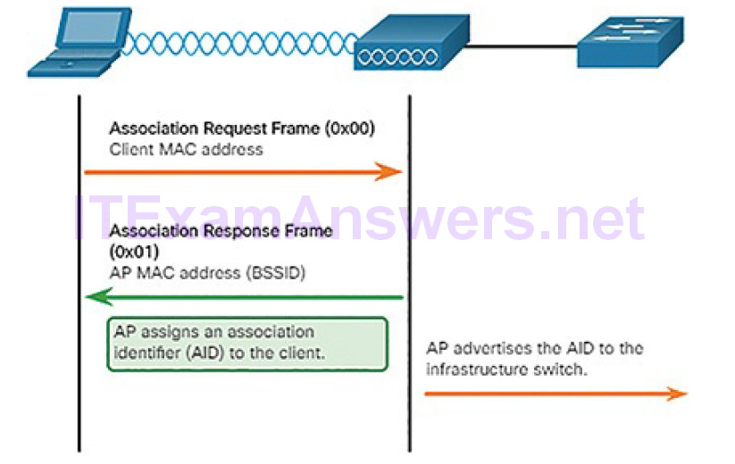
Figure 5-30 Client and AP Associate
As part of this stage:
1. The wireless client forwards an Association Request frame that includes its MAC address.
2. The AP responds with an Association Response that includes the AP BSSID, which is the AP MAC address.
3. The AP maps a logical port known as the association identifier (AID) to the wireless client. The AID is equivalent to a port on a switch and allows the infrastructure switch to keep track of frames destined for the wireless client to be forwarded.
Activity 5.1.2.5: Order the Steps in the Client and AP Association Process
Refer to the online course to complete this Activity.
Wireless Devices: AP, LWAP, WLC (5.1.2.6)
A common wireless data implementation is enabling devices to connect wirelessly via a LAN. In general, a wireless LAN requires wireless access points and clients that have wireless NICs. Home and small business wireless routers integrate the functions of a router, switch, and access point into one device, as shown Figure 5-31. Note that in small networks, the wireless router may be the only AP because only a small area requires wireless coverage. In larger networks, there can be many APs.
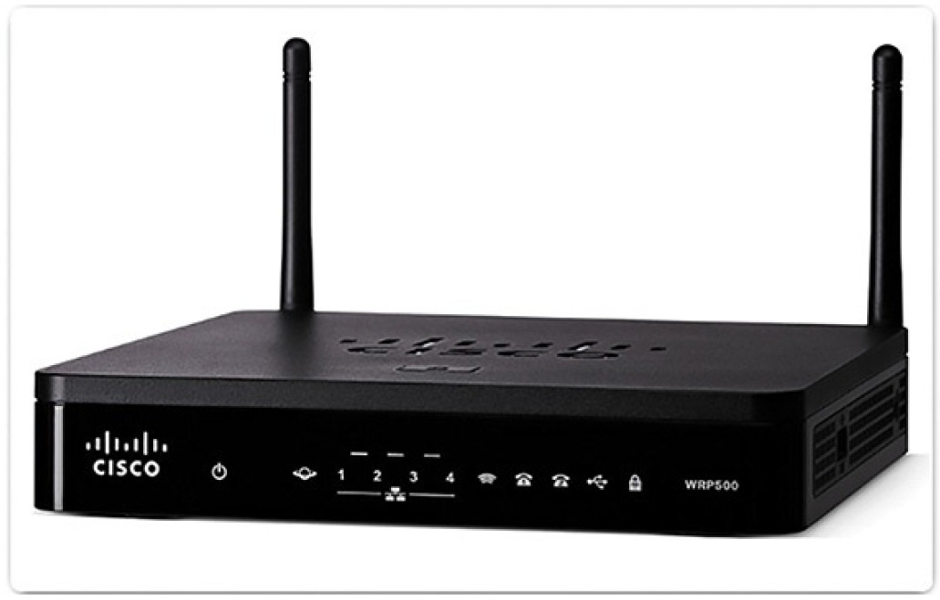
Figure 5-31 Cisco Wireless Router WRP500
All of the control and management functions of the APs on a network can be centralized into a Wireless LAN Controller (WLC). When using a WLC, the APs no longer act autonomously, but instead act as lightweight APs (LWAPs). LWAPs only forward data between the wireless LAN and the WLC. All management functions, such as defining SSIDs and authentication, are conducted on the centralized WLC rather than on each individual AP. A major benefit of centralizing the AP management functions in the WLC is simplified configuration and monitoring of numerous access points, among many other benefits.
Activity 5.1.2.7: Identify the LAN Device
Refer to the online course to complete this Activity.
Network Security Infrastructure (5.2)
In this section, you will learn how devices and services are used to enhance network security.
Security Devices (5.2.1)
In this topic, you will learn how specialized devices are used to enhance network security.
Video Tutorial 5.2.1.1: Security Devices
Refer to the online course to view this video.
Firewalls (5.2.1.2)
A firewall is a system, or group of systems, that enforces an access control policy between networks, as shown in Figure 5-32.
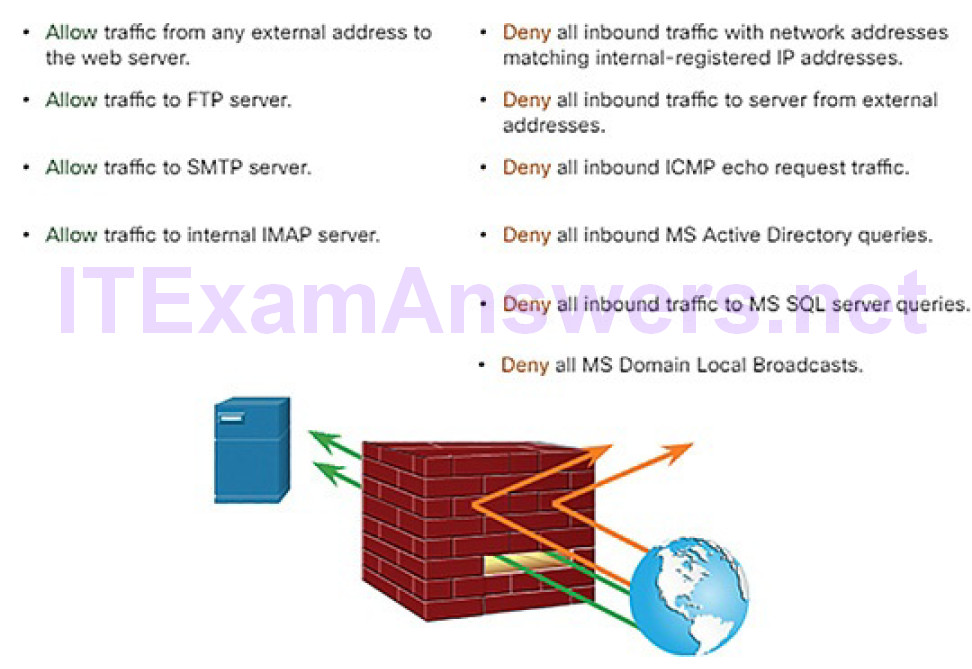
Figure 5-32 Firewall Operation
All firewalls share some common properties:
- Firewalls are resistant to network attacks.
- Firewalls are the only transit point between internal corporate networks andexternal networks because all traffic flows through the firewall.
- Firewalls enforce the access control policy.
There are several benefits of using a firewall in a network:
- They prevent the exposure of sensitive hosts, resources, and applications to untrusted users.
- They sanitize protocol flow, which prevents the exploitation of protocol flaws.
- They block malicious data from servers and clients.
- They reduce security management complexity by off-loading most of the network access control to a few firewalls in the network.
Firewalls also present some limitations:
- A misconfigured firewall can have serious consequences for the network, such as becoming a single point of failure.
- The data from many applications cannot be passed over firewalls securely.
- Users might proactively search for ways around the firewall to receive blocked material, which exposes the network to potential attack.
- Network performance can slow down.
- Unauthorized traffic can be tunneled or hidden as legitimate traffic through the firewall.
Firewall Type Descriptions (5.2.1.3)
It is important to understand the different types of firewalls and their specific capabilities so that the right firewall is used for each situation.
Packet filtering (stateless) firewall: Typically a router with the capability to filter some packet content, such as Layer 3 and sometimes Layer 4 information according to a set of configured rules (Figure 5-33).
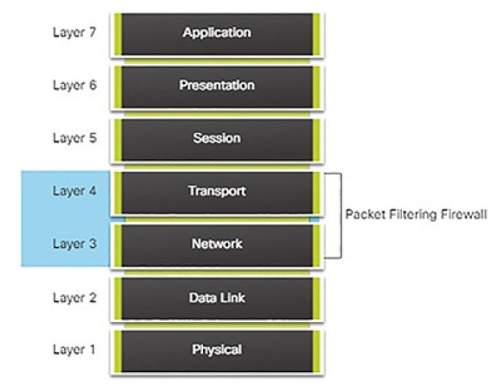
Figure 5-33 Packet Filtering Firewall
Stateful firewall: A stateful inspection firewall allows or blocks traffic based on state, port, and protocol. It monitors all activity from the opening of a connection until it is closed. Filtering decisions are made based on both administrator-defined rules as well as context, which refers to using information from previous connections and packets belonging to the same connection (Figure 5-34).
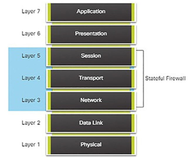
Figure 5-34 Stateful Firewall
Application gateway firewall (proxy firewall): Filters information at Layers 3, 4, 5, and 7 of the OSI reference model. Most of the firewall control and filtering is done in software. When a client needs to access a remote server, it connects to a proxy server. The proxy server connects to the remote server on behalf of the client. Therefore, the server only sees a connection from the proxy server (Figure 5-35).
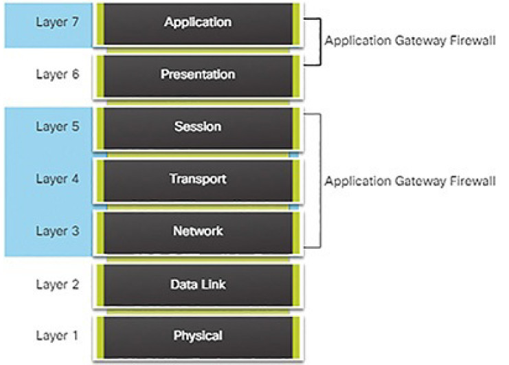
Figure 5-35 Application Gateway Firewall
Other methods of implementing firewalls include:
- Host-based (server and personal) firewall: A PC or server with firewall software running on it.
- Transparent firewall: Filters IP traffic between a pair of bridged interfaces.
- Hybrid firewall: A combination of the various firewall types. For example, an application inspection firewall combines a stateful firewall with an application gateway firewall.
Packet Filtering Firewalls (5.2.1.4)
Packet filtering firewalls are usually part of a router firewall, which permits or denies traffic based on Layer 3 and Layer 4 information. They are statelessfirewalls that use a simple policy table lookup that filters traffic based on specific criteria, as shown in Figure 5-36.
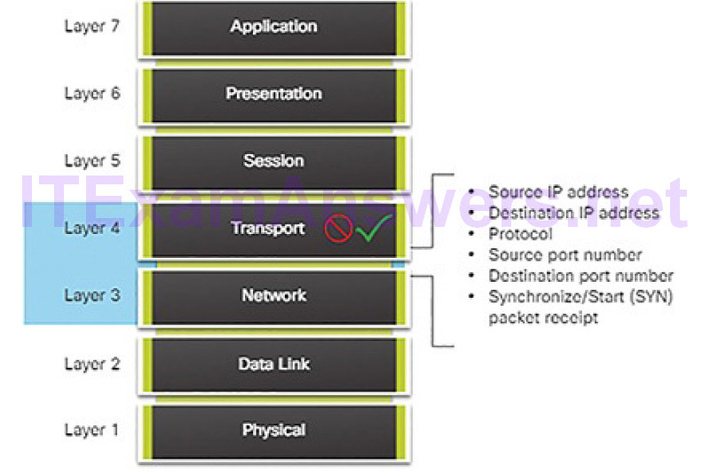
Figure 5-36 Packet Filtering Firewall
For example, SMTP servers listen to port 25 by default. An administrator can configure the packet filtering firewall to block port 25 from a specific workstation to prevent it from broadcasting an email virus.
Stateful Firewalls (5.2.1.5)
Stateful firewalls are the most versatile and the most common firewall technologies in use. Stateful firewalls provide stateful packet filtering by using connection information maintained in a state table. Stateful filtering is a firewall architecture that is classified at the network layer. It also analyzes traffic at OSI Layer 4 and Layer 5, as shown in Figure 5-37.
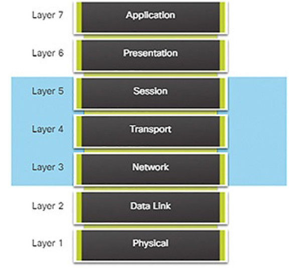
Figure 5-37 Stateful Firewalls and the OSI Model
Next-Generation Firewalls (5.2.1.6)
Next-generation firewalls go beyond stateful firewalls by providing
- Standard firewall capabilities like stateful inspection
- Integrated intrusion prevention
- Application awareness and control to see and block risky apps
- Upgrade paths to include future information feeds
- Techniques to address evolving security threats
Activity 5.2.1.7: Identify the Type of Firewall
Refer to the online course to complete this Activity.
Intrusion Protection and Detection Devices (5.2.1.8)
A networking architecture paradigm shift is required to defend against fast-moving and evolving attacks. This must include cost-effective detection and prevention systems, such as intrusion detection systems (IDS) or the more scalable intrusion prevention systems (IPS). The network architecture integratesthese solutions into the entry and exit points of the network.
When implementing IDS or IPS, it is important to be familiar with the types of systems available, host-based and network-based approaches, the placement of these systems, the role of signature categories, and possible actions that a Cisco IOS router can take when an attack is detected.
IDS and IPS technologies share several characteristics, as shown in Figure 5-38.
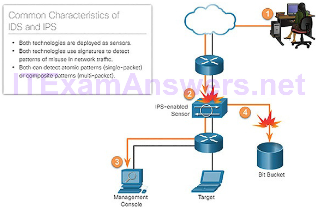
Figure 5-38 IDS and IPS Characteristics
IDS and IPS technologies are both deployed as sensors. An IDS or IPS sensor can be in the form of several different devices:
- A router configured with Cisco IOS IPS software
- A device specifically designed to provide dedicated IDS or IPS services
- A network module installed in a Cisco Adaptive Security Appliance (ASA), switch, or router
IDS and IPS technologies use signatures to detect patterns in network traffic. A signature is a set of rules that an IDS or IPS uses to detect malicious activity. Signatures can be used to detect severe breaches of security, to detect commonnetwork attacks, and to gather information. IDS and IPS technologies can detect atomic signature patterns (single-packet) or composite signature patterns (multi-packet).
Advantages and Disadvantages of IDS and IPS (5.2.1.9)
A list of the advantages and disadvantages of IDS and IPS is shown in Table 5-3.
Table 5-3 Comparing IDS and IPS Solutions
| Advantages | Disadvantage | |
| IDS | No impact on network (latency, jitter). | Response action cannot stop trigger packets. |
| No network impact if there is a sensor failure. | Correct tuning required for response actions. | |
| No network impact if there is a sensor overload. | More vulnerable to network security evasion. | |
| IPS | Stops trigger packets. | Sensor issues might affect network traffic. |
| Can use stream normalization techniques. | Sensor overloading impacts the network. | |
| Some impact on network (latency, jitter). |
IDS Advantages and Disadvantages
A primary advantage of an IDS platform is that it is deployed in offline mode. Because the IDS sensor is not inline, it has no impact on network performance. It does not introduce latency, jitter, or other traffic flow issues. In addition, if a sensor fails it does not affect network functionality. It only affects the ability of the IDS to analyze the data.
However, there are many disadvantages of deploying an IDS platform. An IDS sensor is primarily focused on identifying possible incidents, logginginformation about the incidents, and reporting the incidents. The IDS sensor cannot stop the trigger packet and is not guaranteed to stop a connection. The trigger packet alerts the IDS to a potential threat. IDS sensors are also less helpful in stopping email viruses and automated attacks, such as worms.
Users deploying IDS sensor response actions must have a well-designed security policy and a good operational understanding of their IDS deployments. Users must spend time tuning IDS sensors to achieve expected levels of intrusion detection.
Finally, because IDS sensors are not inline, an IDS implementation is more vulnerable to network security evasion techniques in the form of various network attack methods.
IPS Advantages and Disadvantages
An IPS sensor can be configured to perform a packet drop to stop the trigger packet, the packets associated with a connection, or packets from a source IP address. Additionally, because IPS sensors are inline, they can use stream normalization. Stream normalization is a technique used to reconstruct the data stream when the attack occurs over multiple data segments.
A disadvantage of IPS is that (because it is deployed inline) errors, failure, and overwhelming the IPS sensor with too much traffic can have a negative effect on network performance. An IPS sensor can affect network performance by introducing latency and jitter. An IPS sensor must be appropriately sized and implemented so that time-sensitive applications, such as VoIP, are not adversely affected.
Deployment Considerations
Using one of these technologies does not negate the use of the other. In fact, IDS and IPS technologies can complement each other. For example, an IDS can be implemented to validate IPS operation because the IDS can be configured for deeper packet inspection offline. This allows the IPS to focus on fewer but more critical traffic patterns inline.
Deciding which implementation to use is based on the security goals of the organization as stated in their network security policy.
Types of IPS (5.2.1.10)
There are two primary kinds of IPSs available: host-based and network-based. These IPSs are compared in Table 5-4.
Table 5-4 Comparing Host-Based and Network-Based IPS Solutions
| Advantages | Disadvantages | |
| Host-Based IPS | Provides protection specific to a host operating system | Operating system dependent |
| Provides operating system and application level protection | Must be installed on all hosts | |
| Protects the host after the message is decrypted | ||
| Network-Based IPS | Cost effective | Cannot examine encrypted traffic |
| Operating system independent | Must stop malicious traffic prior to arriving at host |
Host-based IPS
A host-based IPS (HIPS) is software installed on a single host to monitor and analyze suspicious activity. A significant advantage of HIPS is that it can monitor and protect operating system and critical system processes that are specific to that host. With detailed knowledge of the operating system, HIPS can monitor abnormal activity and prevent the host from executing commands that do not match typical behavior. This suspicious or malicious behavior might include unauthorized registry updates, changes to the system directory, executing installation programs, and activities that cause buffer overflows. Network traffic can also be monitored to prevent the host from participating in a denial-of-service (DoS) attack or being part of an illicit FTP session.
A HIPS can be thought of as a combination of antivirus software, antimalware software, and firewall. Combined with a network-based IPS, a HIPS is an effective tool in providing additional protection for the host.
A disadvantage of a HIPS is that it operates only at a local level. It does not have a complete view of the network, or coordinated events that might be happening across the network. To be effective in a network, a HIPS must be installed on every host and have support for every operating system.
Network-based IPS
A network-based IPS can be implemented using a dedicated or non-dedicated IPS device. Network-based IPS implementations are a critical component of intrusion prevention. There are host-based IDS/IPS solutions, but these must be integrated with a network-based IPS implementation to ensure a robust security architecture.
Sensors detect malicious and unauthorized activity in real time and can take action when required. Sensors are deployed at designated network points (Figure 5-39) that enable security managers to monitor network activity while it is occurring, regardless of the location of the attack target.
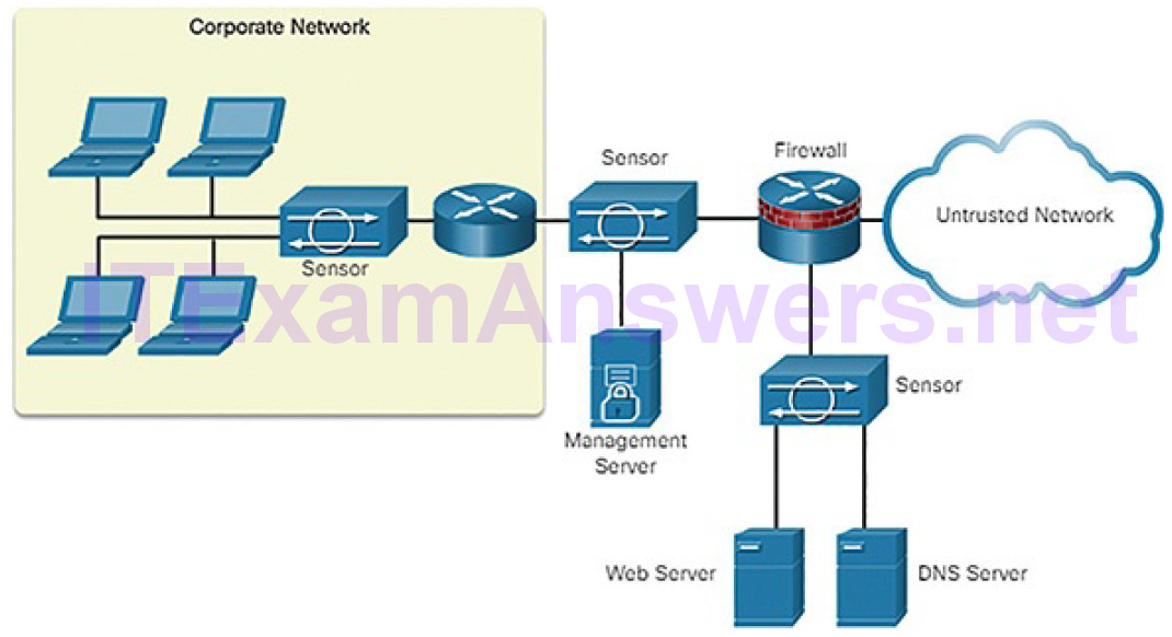
Figure 5-39 Sample IPS Sensor Deployment
Specialized Security Appliances (5.2.1.11)
Cisco Advanced Malware Protection (AMP) is an enterprise-class advanced malware analysis and protection solution. It provides comprehensive malwareprotection for organizations before, during, and after an attack:
- Before an attack, AMP strengthens defenses and protects against known and emerging threats.
- During an attack, AMP identifies and blocks policy-violating file types, exploit attempts, and malicious files from infiltrating the network.
- After an attack, or after a file is initially inspected, AMP goes beyond point-in-time detection capabilities and continuously monitors and analyzes all file activity and traffic, regardless of disposition, searching for any indications of malicious behavior. If a file with an unknown or previously deemed “good” disposition starts behaving badly, AMP will detect it and instantly alert security teams with an indication of compromise. It then provides visibility into where the malware originated, what systems were affected, and what the malware is doing.
AMP accesses the collective security intelligence of the Cisco Talos Security Intelligence and Research Group. Talos detects and correlates threats in real time using the largest threat-detection network in the world.
Cisco Web Security Appliance (WSA) is a secure web gateway that combines leading protections to help organizations address the growing challenges of securing and controlling web traffic. WSA protects the network by automatically blocking risky sites and testing unknown sites before allowing users to access them. WSA provides malware protection, application visibility and control, acceptable use policy controls, insightful reporting, and secure mobility.
While WSA protects the network from malware intrusion, it does not provide protection for users who want to connect to the Internet directly outside of the protected network, such as at a public Wi-Fi service. In this instance, the user’s PC can be infected with malware, which can then spread to other networks and devices. To help protect user PCs from these types of malware infections there is Cisco Cloud Web Security (CWS).
CWS together with WSA provides comprehensive protection against malware and the associated impacts. The Cisco CWS solution enforces secure communication to and from the Internet and provides remote workers the same level of security as onsite employees when using a laptop issued by Cisco. Cisco CWS incorporates two main functions, web filtering and web security, and both are accompanied by extensive, centralized reporting.
Cisco Email Security Appliance (ESA)/Cisco Cloud Email Security help tomitigate email-based threats. The Cisco ESA defends mission-critical email systems. The Cisco ESA is constantly updated by real-time feeds from Cisco Talos, which detects and correlates threats using a worldwide database monitoring system. These are some of the main features of ESA:
- Global threat intelligence: Cisco Talos provides a 24-hour view into global traffic activity. It analyzes anomalies, uncovers new threats, and monitors traffic trends.
- Spam blocking: A multilayered defense combines an outer layer of filtering based on the reputation of the sender and an inner layer of filtering that performs a deep analysis of the message.
- Advanced malware protection: Includes AMP that takes advantage of the vast cloud security intelligence network of Sourcefire. It delivers protection across the attack continuum before, during, and after an attack.
- Outbound message control: Controls outbound messages to help ensure that important messages comply with industry standards and are protected in transit.
Activity 5.2.1.12: Compare IDS and IPS Characteristics
Refer to the online course to complete this Activity.
Security Services (5.2.2)
In this topic, you will learn how network services enhance network security.
Video Tutorial 5.2.2.1: Security Services
Refer to the online course to view this video.
Traffic Control with ACLs (5.2.2.2)
An access control list (ACL) is a series of commands that control whether a device forwards or drops packets based on information found in the packet header. When configured, ACLs perform the following tasks:
- They limit network traffic to increase network performance. For example, if corporate policy does not allow video traffic on the network, ACLs that block video traffic could be configured and applied. This would greatly reduce the network load and increase network performance.
- They provide traffic flow control. ACLs can restrict the delivery of routing updates to ensure that the updates are from a known source.
- They provide a basic level of security for network access. ACLs can allow one host to access a part of the network and prevent another host from accessing the same area. For example, access to the Human Resources network can be restricted to authorized users.
- They filter traffic based on traffic type. For example, an ACL can permit email traffic, but block all Telnet traffic.
- They screen hosts to permit or deny access to network services. ACLs can permit or deny a user to access file types, such as FTP or HTTP.
In addition to either permitting or denying traffic, ACLs can be used for selecting types of traffic to be analyzed, forwarded, or processed in other ways. For example, ACLs can be used to classify traffic to enable priority processing. This capability is similar to having a VIP pass at a concert or sporting event. The VIP pass gives selected guests privileges not offered to general admission ticket holders, such as priority entry or being able to enter a restricted area.
Figure 5-40 shows a sample topology with ACLs applied to routers R1, R2, and R3.
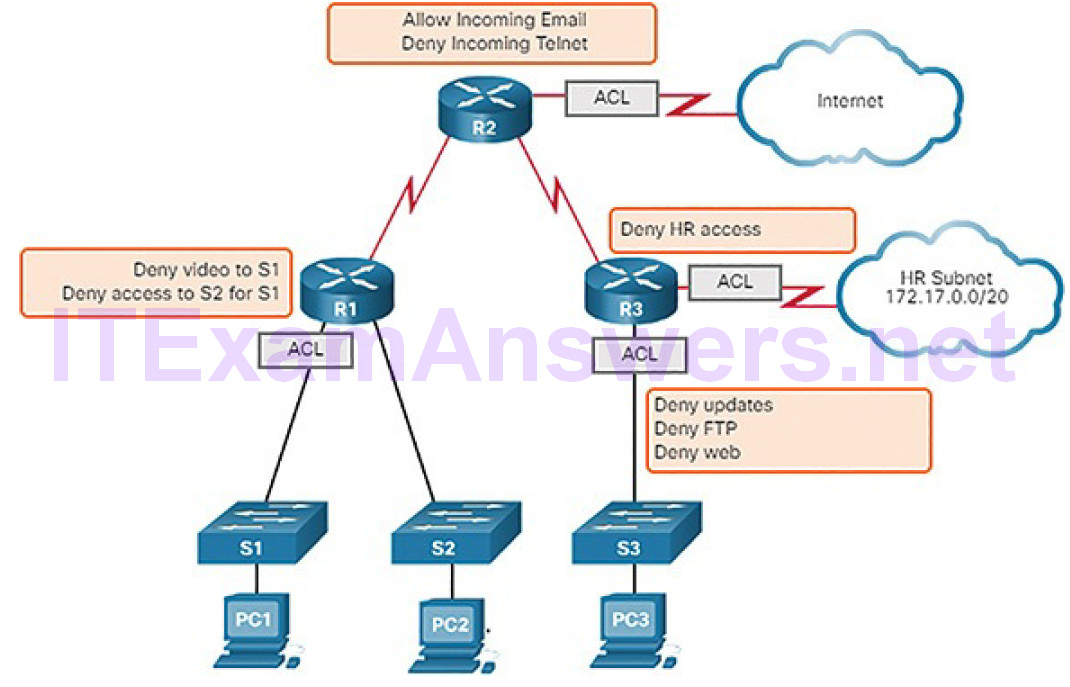
Figure 5-40 What Is an ACL?
ACLs: Important Features (5.2.2.3)
Two types of Cisco IPv4 ACLs are standard and extended. Standard ACLs can be used to permit or deny traffic only from source IPv4 addresses. The destination of the packet and the ports involved are not evaluated.
Extended ACLs filter IPv4 packets based on several attributes that include:
- Protocol type
- Source IPv4 address
- Destination IPv4 address
- Source TCP or UDP ports
- Destination TCP or UDP ports
- Optional protocol type information for finer control
Standard and extended ACLs can be created using either a number or a name to identify the ACL and its list of statements.
Using numbered ACLs is an effective method for determining the ACL type onsmaller networks with more homogeneously defined traffic. However, a number does not provide information about the purpose of the ACL. For this reason, a name can be used to identify a Cisco ACL.
By configuring ACL logging, an ACL message can be generated and logged when traffic meets the permit or deny criteria defined in the ACL.
Cisco ACLs can also be configured to only allow TCP traffic that has an ACK or RST bit set, so that only traffic from an established TCP session is permitted. This can be used to deny any TCP traffic from outside the network that is trying to establish a new TCP session.
Packet Tracer 5.2.2.4: ACL Demonstration
In this activity, you will observe how an access control list (ACL) can be used to prevent a ping from reaching hosts on remote networks. After removing the ACL from the configuration, the pings will be successful.
SNMP (5.2.2.5)
Simple Network Management Protocol (SNMP) allows administrators to manage end devices, such as servers, workstations, routers, switches, and security appliances, on an IP network. It enables network administrators to monitor and manage network performance, find and solve network problems, and plan for network growth.
SNMP is an application layer protocol that provides a message format for communication between managers and agents. The SNMP system consists of three elements, as shown in Figure 5-41:
- SNMP manager: Runs SNMP management software
- SNMP agents: The nodes being monitored and managed
- Management Information Base (MIB): A database on the agent that stores data and operational statistics about the device
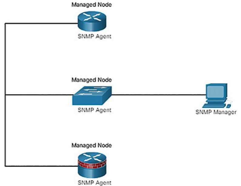
Figure 5-41 SNMP Topology
NetFlow (5.2.2.6)
NetFlow is a Cisco IOS technology that provides statistics on packets flowing through a Cisco router or multilayer switch. While SNMP attempts to provide a very wide range of network management features and options, NetFlow is focused on providing statistics on IP packets flowing through network devices.
NetFlow provides data to enable network and security monitoring, network planning, traffic analysis to include identification of network bottlenecks, and IP accounting for billing purposes. For example, in Figure 5-42, PC1 connects to PC2 using an application such as HTTPS. NetFlow can monitor that application connection, tracking byte and packet counts for that individual application flow.
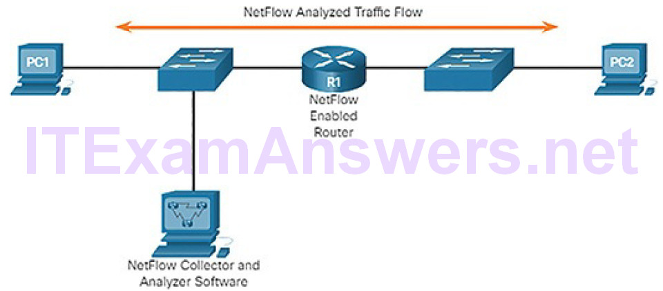
Figure 5-42 NetFlow in the Network
NetFlow technology has seen several generations that provide more sophistication in defining traffic flows, but “original NetFlow” distinguished flows using a combination of seven fields. Should one of these fields vary in value from another packet, the packets could be safely determined to be from different flows:
- Source IP address
- Destination IP address
- Source port number
- Destination port number
- Layer 3 protocol type
- Type of Service (ToS) marking
- Input logical interface
The first four of the fields NetFlow uses to identify a flow should be familiar. The source and destination IP addresses, plus the source and destination ports, identify the connection between source and destination application. The Layer 3 protocol type identifies the type of header that follows the IP header (usually TCP or UDP, but other options include ICMP). The ToS byte in the IPv4 header holds information about how devices should apply quality of service (QoS) rules to the packets in that flow.
Port Mirroring (5.2.2.7)
A packet analyzer (also known as a packet sniffer or traffic sniffer) is typically software that captures packets entering and exiting the network interface card (NIC). It is not always possible or desirable to have the packet analyzer on the device that is being monitored. Sometimes it is better on a separate station designated to capture the packets.
Because network switches can isolate traffic, traffic sniffers or other network monitors, such as IDS, cannot access all the traffic on a network segment. Port mirroring is a feature that allows a switch to make duplicate copies of traffic passing through a switch, and then send it out a port with a network monitor attached. The original traffic is forwarded in the usual manner. An example of port mirroring is illustrated in Figure 5-43.
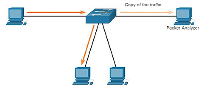
Figure 5-43 Traffic Sniffing Using a Switch
Syslog Servers (5.2.2.8)
When certain events occur on a network, networking devices have trusted mechanisms to notify the administrator with detailed system messages. These messages can be either noncritical or significant. Network administrators have a variety of options for storing, interpreting, and displaying these messages, and for being alerted to those messages that could have the greatest impact on the network infrastructure.
The most common method of accessing system messages is to use a protocol called syslog.
Many networking devices support syslog, including routers, switches, application servers, firewalls, and other network appliances. The syslog protocol allows networking devices to send their system messages across the network tosyslog servers as shown in Figure 5-44.
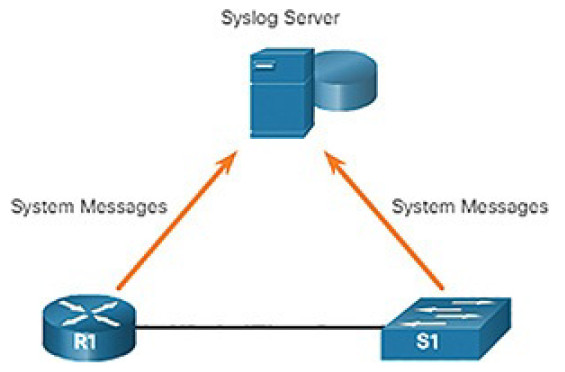
Figure 5-44 Syslog
The syslog logging service provides three primary functions:
- The ability to gather logging information for monitoring and troubleshooting
- The ability to select the type of logging information that is captured
- The ability to specify the destination of captured syslog messages
NTP (5.2.2.9)
It is important to synchronize the time across all devices on the network because all aspects of managing, securing, troubleshooting, and planning networks require accurate and consistent timestamping. When the time is not synchronized between devices, it will be impossible to determine the order of the events that have occurred in different parts of the network.
Typically, the date and time settings on a network device can be set using one of two methods:
- Manual configuration of the date and time
- Configuring the Network Time Protocol (NTP)
As a network grows, it becomes difficult to ensure that all infrastructure devices are operating with synchronized time. Even in a smaller network environment, the manual method is not ideal. If a device reboots, how will it get an accuratedate and timestamp?
A better solution is to configure NTP on the network. This protocol allows routers on the network to synchronize their time settings with an NTP server. A group of NTP clients that obtain time and date information from a single source have more consistent time settings. When NTP is implemented in the network, it can be set up to synchronize to a private master clock or it can synchronize to a publicly available NTP server on the Internet.
NTP networks use a hierarchical system of time sources. Each level in this hierarchical system is called a stratum. The stratum level is defined as the number of hop counts from the authoritative source. The synchronized time is distributed across the network using NTP. Figure 5-45 displays a sample NTP network.
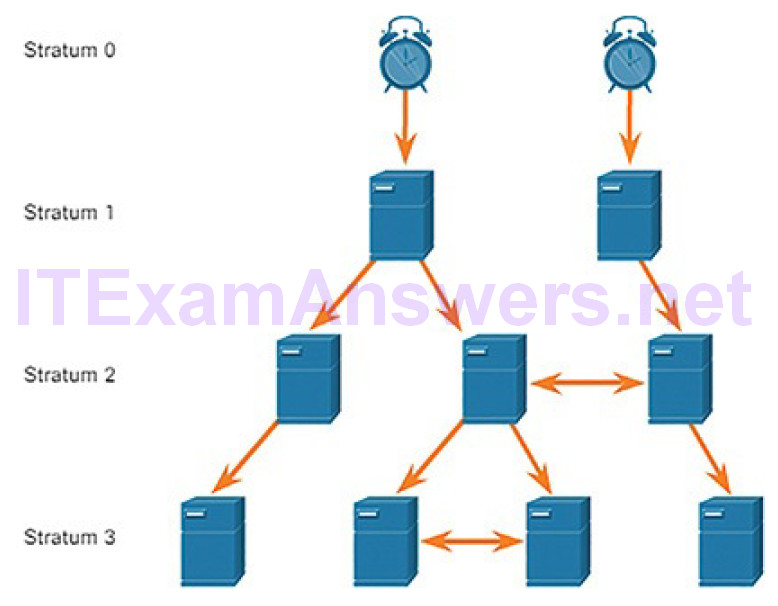
Figure 5-45 NTP Stratum Labels
NTP servers are arranged in three levels known as strata:
- Stratum 0: An NTP network gets the time from authoritative time sources. These authoritative time sources, also referred to as stratum 0 devices, are high-precision timekeeping devices assumed to be accurate and with little or no delay associated with them.
- Stratum 1: The stratum 1 devices are directly connected to theauthoritative time sources. They act as the primary network time standard.
- Stratum 2 and lower: The stratum 2 servers are connected to stratum 1 devices through network connections. Stratum 2 devices, such as NTP clients, synchronize their time using the NTP packets from stratum 1 servers. They could also act as servers for stratum 3 devices.
Smaller stratum numbers indicate that the server is closer to the authorized time source than larger stratum numbers. The larger the stratum number, the lower the stratum level. The max hop count is 15. Stratum 16, the lowest stratum level, indicates that a device is unsynchronized. Time servers on the same stratum level can be configured to act as a peer with other time servers on the same stratum level for backup or verification of time.
AAA Servers (5.2.2.10)
AAA is an architectural framework for configuring a set of three independent security functions:
- Authentication: Users and administrators must prove that they are who they say they are. Authentication can be established using username and password combinations, challenge and response questions, token cards, and other methods. For example: “I am user ‘student’ and I know the password to prove it.” AAA authentication provides a centralized way to control access to the network.
- Authorization: After the user is authenticated, authorization services determine which resources the user can access and which operations the user is allowed to perform. An example is “User ‘student’ can access host serverXYZ using SSH only.”
- Accounting and auditing: Accounting records what the user does, including what is accessed, the amount of time the resource is accessed, and any changes that were made. Accounting keeps track of how network resources are used. An example is “User ‘student’ accessed host serverXYZ using SSH for 15 minutes.”
Terminal Access Controller Access-Control System Plus (TACACS+) and Remote Authentication Dial-In User Service (RADIUS) are both authentication protocols that are used to communicate with AAA servers. Whether TACACS+ or RADIUS is selected depends on the needs of the organization.
While both protocols can be used to communicate between a router and AAA servers, TACACS+ is considered the more secure protocol. This is because all TACACS+ protocol exchanges are encrypted, while RADIUS only encrypts the user’s password. RADIUS does not encrypt usernames, accounting information, or any other information carried in the RADIUS message. Table 5-5 shows differences between the two protocols.
Table 5-5 TACACS+ versus RADIUS
| TACACS+ | RADIUS | |
| Functionality | Separates AAA according to the AAA architecture, allowing modularity of the security server implementation | Combines authentication and authorization but separates accounting, allowing less flexibility in implementation than TACACS+ |
| Standard | Mostly Cisco supported | Open/RFC standard |
| Transport Protocol | TCP | UDP |
| CHAP | Bidirectional challenge and response as used in Challenge Handshake Authentication Protocol (CHAP) | Unidirectional challenge and response from the RADIUS security server to the RADIUS client |
| Confidentiality | Entire packet encrypted | Password encrypted |
| Customization | Provides authorization of router commands on a per-user or per-group basis | Has no option to authorize router commands on a per-user or per-group basis |
| Accounting | Limited | Extensive |
VPN (5.2.2.11)
A virtual private network (VPN) is a private network that is created over a public network, usually the Internet, as shown in Figure 5-46.
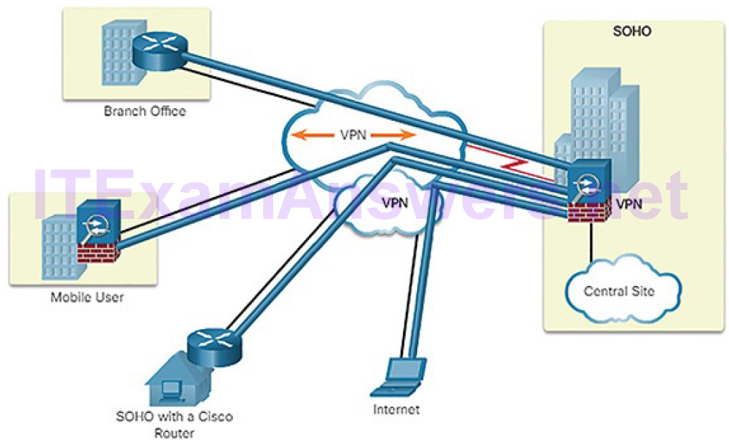
Figure 5-46 Virtual Private Networks
Instead of using a dedicated physical connection, a VPN uses virtual connections routed through the Internet from the organization to the remote site. The first VPNs were strictly IP tunnels that did not include authentication or encryption of the data. For example, Generic Routing Encapsulation (GRE) is a tunneling protocol developed by Cisco that can encapsulate a wide variety of network layer protocol packet types inside IP tunnels. This creates a virtual point-to-point link to Cisco routers at remote points over an IP internetwork.
A VPN is virtual in that it carries information within a private network, but that information is actually transported over a public network. A VPN is private in that the traffic is encrypted to keep the data confidential while it is transported across the public network.
A VPN is a communications environment in which access is strictly controlled to permit peer connections within a defined community of interest. Confidentiality is achieved by encrypting the traffic within the VPN. Today, a secure implementation of VPN with encryption is what is generally equated with the concept of virtual private networking.
In the simplest sense, a VPN connects two endpoints, such as a remote office to a central office, over a public network, to form a logical connection. The logical connections can be made at either Layer 2 or Layer 3. Common examples ofLayer 3 VPNs are GRE, Multiprotocol Label Switching (MPLS), and IPsec.
Layer 3 VPNs can be point-to-point site connections, such as GRE and IPsec, or they can establish any-to-any connectivity to many sites using MPLS.
IPsec is a suite of protocols developed with the backing of the IETF to achieve secure services over IP packet-switched networks, as shown in Figure 5-47.
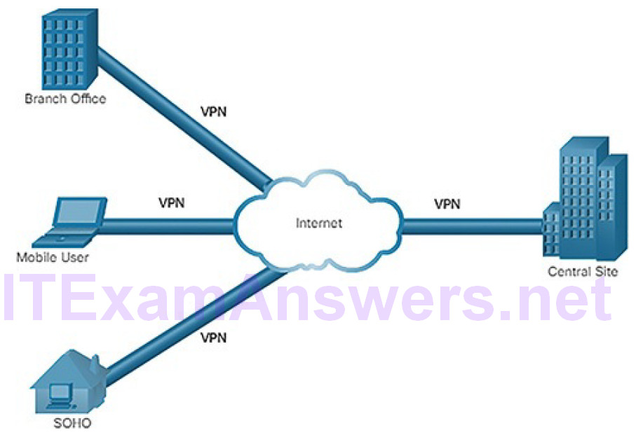
Figure 5-47 IPsec VPN
IPsec services allow for authentication, integrity, access control, and confidentiality. With IPsec, the information exchanged between remote sites can be encrypted and verified. Both remote-access and site-to-site VPNs can be deployed using IPsec.
Activity 5.2.2.12: Identify the Network Security Device or Service
Refer to the online course to complete this Activity.
Network Representations (5.3)
In this section, you will learn how networks and network topologies are represented.
Network Topologies (5.3.1)
In this topic, you will learn how network designs are represented by interconnected symbols.
Overview of Network Components (5.3.1.1)
The path that a message takes from source to destination can be as simple as a single cable connecting one computer to another, or as complex as a collection of networks that literally spans the globe. This network infrastructure provides the stable and reliable channel over which these communications occur.
The network infrastructure contains three categories of network components:
Devices (Figure 5-48)
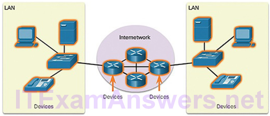
Figure 5-48 Components of a Network: Devices
Media (Figure 5-49)
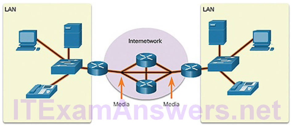
Figure 5-49 Components of a Network: Media
Services (Figure 5-50)
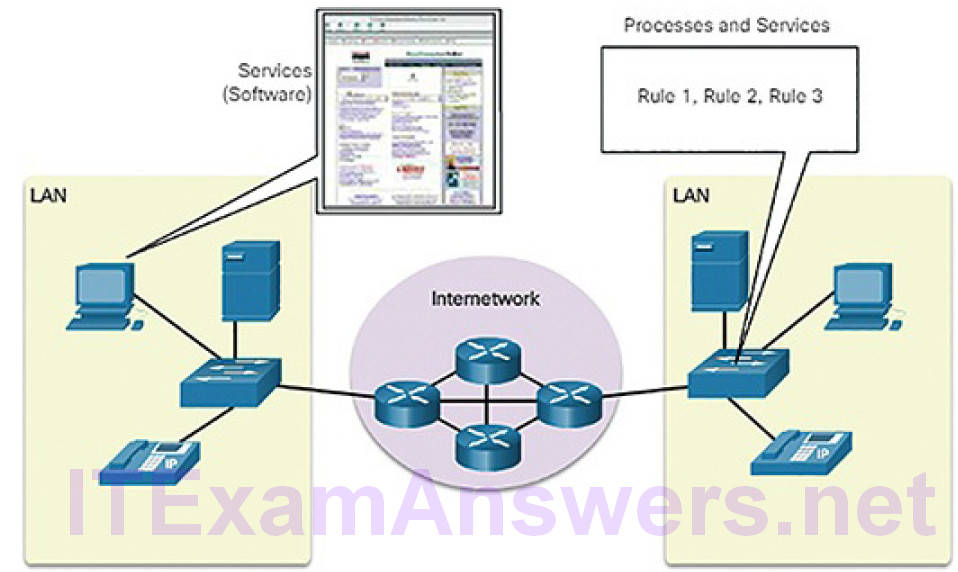
Figure 5-50 Components of a Network: Services and Processes
Devices and media are the physical elements, or hardware, of the network. Hardware is often the visible components of the network platform such as a laptop, PC, switch, router, wireless access point, or the cabling used to connect the devices.
Services include many of the common network applications people use everyday, like email hosting services and web hosting services. Processes provide the functionality that directs and moves the messages through the network. Processes are less obvious to us but are critical to the operation of networks.
Physical and Logical Topologies (5.3.1.2)
The topology of a network is the arrangement or relationship of the network devices and the interconnections between them. LAN and wide area network (WAN) topologies can be viewed in two ways:
Physical topology: Refers to the physical connections and identifies how end devices and infrastructure devices such as routers, switches, and wireless access points are interconnected (Figure 5-51).
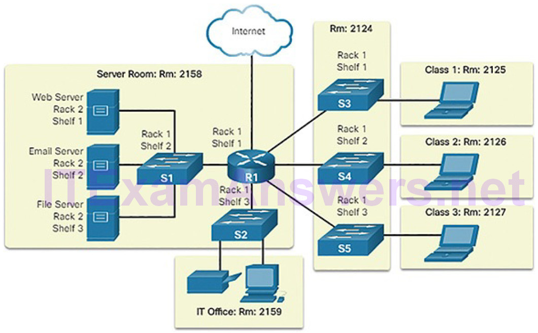
Figure 5-51 Physical Topology
Logical topology: Refers to the way a network transfers frames from one node to the next. This arrangement consists of virtual connections between the nodes of a network. These logical signal paths are defined by data link layer protocols. The logical topology of point-to-point links is relatively simple, while shared media offers different access control methods (Figure5-52).
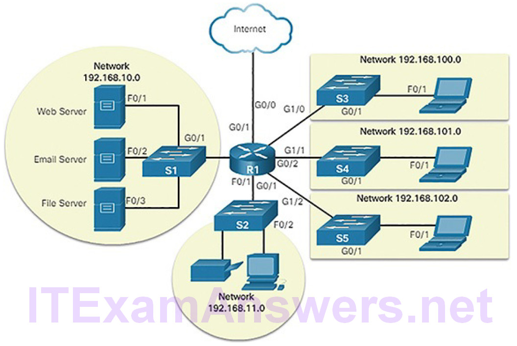
Figure 5-52 Logical Topology
The data link layer “sees” the logical topology of a network when controlling data accesses the media. It is the logical topology that influences the type of network framing and media access control used.
WAN Topologies (5.3.1.3)
WANs are commonly interconnected using the following physical topologies:
- Point-to-point: This is the simplest topology. It consists of a permanent link between two endpoints. For this reason, this is a very popular WAN topology.
- Hub and spoke: This topology is a WAN version of the star topology in which a central site interconnects branch sites using point-to-point links.
- Mesh: This topology provides high availability, but requires that every end system be interconnected to every other system. Therefore, theadministrative and physical costs can be significant. Each link is essentially a point-to-point link to the other node.
The three common physical WAN topologies are illustrated in Figure 5-53.

Figure 5-53 WAN Physical Topologies
A hybrid is a variation or combination of any of the above topologies. For example, a partial mesh is a hybrid topology in which some, but not all, end devices are interconnected.
LAN Topologies (5.3.1.4)
Physical topology defines how the end systems are physically interconnected. In shared media LANs, end devices can be interconnected using the following physical topologies:
Star: End devices are connected to a central intermediate device. Early star topologies interconnected end devices using Ethernet hubs. However, star topologies now use Ethernet switches. The star topology is easy to install, very scalable (easy to add and remove end devices), and easy to troubleshoot.
Extended star: In an extended star topology, additional Ethernet switches interconnect other star topologies. An extended star is an example of a hybrid topology.
Bus: All end systems are chained to each other and terminated in some form on each end. Infrastructure devices such as switches are not required to interconnect the end devices. Bus topologies using coaxial cables were used in legacy Ethernet networks because it was inexpensive and easy to setup.
Ring: End systems are connected to their respective neighbors, forming a ring. Unlike the bus topology, the ring does not need to be terminated. Ring topologies were used in legacy Fiber Distributed Data Interface (FDDI) and Token Ring networks.
Figure 5-54 illustrates how end devices are interconnected on LANs.
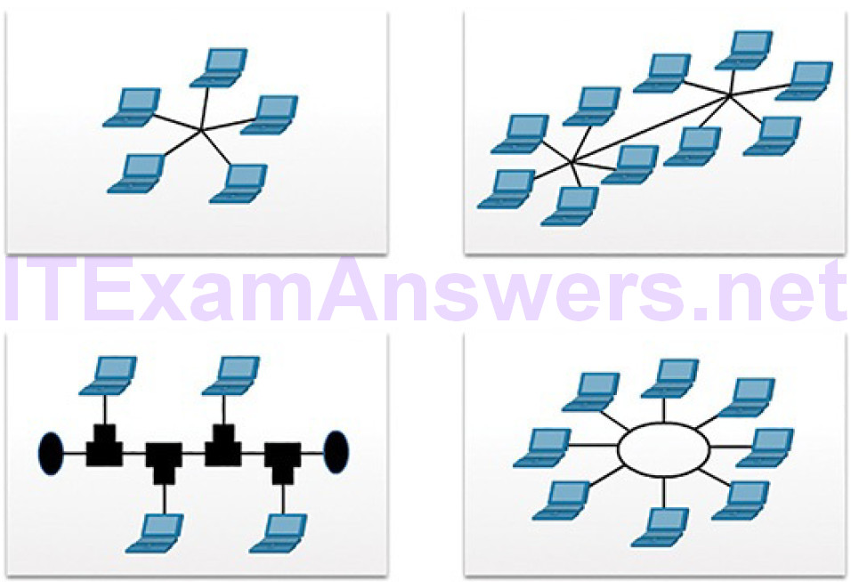
Figure 5-54 LAN Physical Topologies
The Three-Layer Network Design Model (5.3.1.5)
The campus wired LAN uses a hierarchical design model to break the design up into modular groups or layers. Breaking the design up into layers allows each layer to implement specific functions, which simplifies the network design and, therefore, the deployment and management of the network.
The campus wired LAN enables communications between devices in a building or group of buildings, as well as interconnection to the WAN and Internet edge at the network core.
A hierarchical LAN design includes the following three layers, as shown inFigure 5-55:
Access layer: Provides endpoints and users direct access to the network
Distribution layer: Aggregates access layers and provides connectivity to services
Core layer: Provides connectivity between distribution layers for large LAN environments
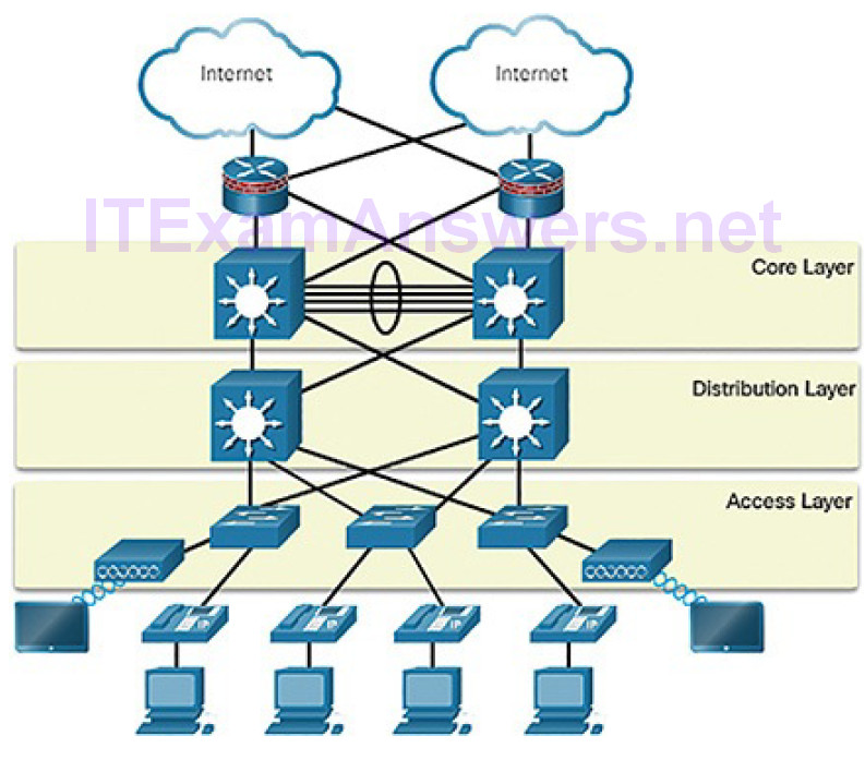
Figure 5-55 Hierarchical Design Model
User traffic is initiated at the access layer and passes through the other layers if the functionality of those layers is required. Even though the hierarchical model has three layers, some smaller enterprise networks may implement a two-tier hierarchical design. In a two-tier hierarchical design, the core and distribution layers are collapsed into one layer, reducing cost and complexity, as shown in
Figure 5-56.
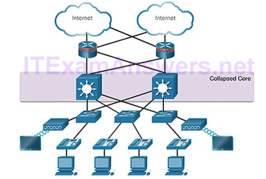
Figure 5-56 Collapsed Core
In flat or meshed network architectures, changes tend to affect a large number of systems. Hierarchical design helps constrain operational changes to a subset of the network, which makes it easy to manage as well as improve resiliency. Modular structuring of the network into small, easy-to-understand elements also facilitates resiliency via improved fault isolation.
Video Tutorial 5.3.1.6: Three-Layer Network Design
Refer to the online course to view this video.
Common Security Architectures (5.3.1.7)
Firewall design is primarily about device interfaces permitting or denying traffic based on the source, the destination, and the type of traffic. Some designs are as simple as designating an outside network and inside network, which are determined by two interfaces on a firewall. As shown in Figure 5-57, the public network (or outside network) is untrusted, and the private network (or inside network) is trusted.

Figure 5-57 Private and Public Networks
Typically, a firewall with two interfaces is configured as follows:
- Traffic originating from the private network is permitted and inspected as it travels toward the public network. Inspected traffic returning from the public network and associated with traffic that originated from the private network is permitted.
- Traffic originating from the public network and traveling to the private network is generally blocked.
A demilitarized zone (DMZ) is a firewall design where there is typically one inside interface connected to the private network, one outside interface connected to the public network, and one DMZ interface, as shown in Figure 5-58.
- Traffic originating from the private network is inspected as it travels toward the public or DMZ network. This traffic is permitted with little or no restriction. Inspected traffic returning from the DMZ or public network to the private network is permitted.
- Traffic originating from the DMZ network and traveling to the private network is usually blocked.
- Traffic originating from the DMZ network and traveling to the public network is selectively permitted based on service requirements.
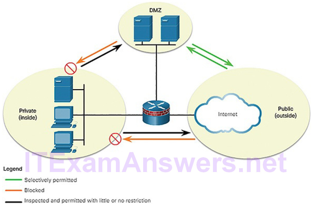
Figure 5-58 Permitted, Blocked, and Inspected Traffic
- Traffic originating from the public network and traveling toward the DMZ is selectively permitted and inspected. This type of traffic is typically email, DNS, HTTP, or HTTPS traffic. Return traffic from the DMZ to the public network is dynamically permitted.
- Traffic originating from the public network and traveling to the private network is blocked.
Zone-based policy firewalls (ZPFs) use the concept of zones to provide additional flexibility. A zone is a group of one or more interfaces that have similar functions or features. Zones help you specify where a Cisco IOS firewall rule or policy should be applied. In Figure 5-59, security policies for LAN 1 and LAN 2 are similar and can be grouped into a zone for firewall configurations. By default, the traffic between interfaces in the same zone is not subject to any policy and passes freely. However, all zone-to-zone traffic is blocked. In order to permit traffic between zones, a policy allowing or inspecting traffic must be configured.
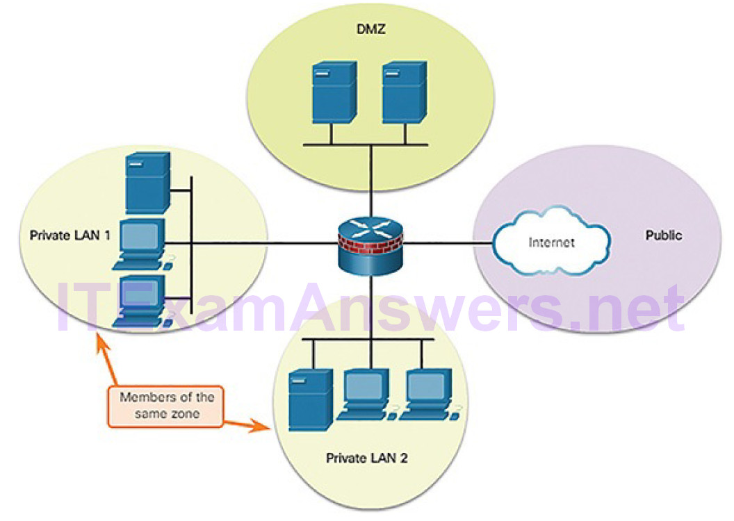
Figure 5-59 Zone-Based Policy Firewalls
The only exception to this default deny any policy is the router self zone. The self zone is the router itself and includes all the router interface IP addresses. Policy configurations that include the self zone would apply to traffic destined to and sourced from the router. By default, there is no policy for this type of traffic. Traffic that should be considered when designing a policy for the self zone includes management plane and control plane traffic, such as SSH, SNMP, and routing protocols.
Activity 5.3.1.8: Identify the Network Topology
Refer to the online course to complete this Activity.
Activity 5.3.1.9: Identify the Network Design Terminology
Refer to the online course to complete this Activity.
Packet Tracer 5.3.1.10: Identify Packet Flow
In this Packet Tracer activity, you will observe packet flow in a LAN and WAN topology. You will also observe how the packet flow path may change when there is a change in the network topology.
Summary (5.4)
In this chapter, you learned the basic operation of the network infrastructure. Routers are network layer devices and use the process of routing to forward data packets between networks or subnetworks. Switches segment a LAN into separate collision domains, one for each switch port. A switch makes forwarding decisions based on Ethernet MAC addresses. Multilayer switches (also known as Layer 3 switches) not only perform Layer 2 switching, but also forward frames based on Layer 3 and 4 information. Wireless networking devices, such as an AP or WLC, use the 802.11 standard instead of the 802.3 standard to connect wireless devices to the network.
Various types of firewalls enable network security, including
- Packet filtering (stateless) firewall: This provides Layer 3 and sometimes Layer 4 filtering.
- Stateful firewall: A stateful inspection firewall allows or blocks traffic based on state, port, and protocol.
- Application gateway firewall (proxy firewall): This filters information at Layers 3, 4, 5, and 7.
Network security services enhance network security through the use of the following:
- ACLs: These are a series of commands that control whether a device forwards or drops packets based on information found in the packet header.
- SNMP: This service enables network administrators to monitor and manage network performance, find and solve network problems, and plan for network growth.
- NetFlow: This provides statistics on packets flowing through a Cisco router or multilayer switch.
- Port mirroring: This is a feature that allows a switch to make duplicate copies of traffic passing through a switch, and then send it out a port with a network monitor attached.
- Syslog server: Use this to access the system messages generated by networking devices.
- NTP: This will synchronize the time across all devices on the network to ensure accurate and consistent timestamping of system messages.
- AAA: This is a framework for configuring user authentication, authorization, and accounting services.
- VPN: This is a private network created between two endpoints across a public network.
Network topologies are typically represented as physical networks and logical networks. A physical network topology refers to the physical connections and identifies how end devices are connected. A logical topology refers to the standards and protocols that devices use to communicate. Most topologies are a combination of both, showing how devices are physically and logically connected.
When looking at a topology that has access to outside or public networks, you should be able to determine the security architecture. Some designs are as simple as designating an outside network and inside network, which are determined by two interfaces on a firewall. Networks that require public access to services will often include a DMZ that the public can access, while strictly blocking access to the inside network. ZPFs use the concept of zones to provide additional flexibility. A zone is a group of one or more interfaces that have similar functions or features.
Practice
The following activities provide practice with the topics introduced in this chapter. The Packet Tracer Activities are available in the companion CCNA Cybersecurity Operations Lab Manual (ISBN: 9781587134388). The PKA files are found in the online course.
Packet Tracer Activities
Packet Tracer 5.2.2.4: ACL Demonstration
Packet Tracer 5.3.1.10: Identify Packet Flow
