Section 42 Tasks
- Read today’s lesson notes (below)
- Review yesterday’s lesson notes
- Complete today’s lab
- Read the ICND2 cram guide
- Spend 15 minutes on the subnetting.org website
Frame Relay was an important part of the CCNA to CCIE syllabus for several years; however, its popularity has waned recently due to the wide availability of DSL connections for businesses and the price of leased lines becoming more affordable. We cover it here because it is included in the CCNA syllabus. PPP is still widely used.
Today you will learn about the following:
- Frame Relay operations
- Configuring Frame Relay
- Troubleshooting Frame Relay
- PPP operations
- Configuring PPP
- Troubleshooting PPP
This lesson maps to the following CCNA syllabus requirements:
- Identify different WAN technologies
- Frame Relay
- Configure and verify a PPP connection between Cisco routers
Frame Relay Operations
Frame Relay is a Layer 2 WAN protocol based on an older protocol called X.25, which is still used by ATMs due to its extensive error-checking capabilities. Frame Relay is comprised of one physical circuit upon which many logical circuits can form. Connections are made on an asneeded basis. An example of a Frame Relay network is illustrated below:
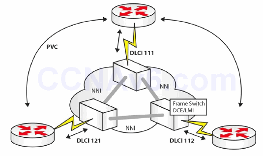
Figure 42.1 – A Frame Relay Network
Common Frame Relay Terms
LMI
Local Management Interface (LMI) is a keepalive which runs from the Frame Relay switch. This switch belongs to your service provider and is located at their premises. You will need to specify the LMI type on your router, unless the CISCO default is used. The three types of LMIs available are as follows:
- CISCO
- ANSI
- Q933a
LMIs are illustrated in Figure 42.2 below:
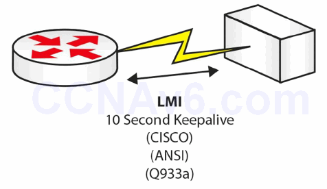
Figure 42.2 – LMI Types
If you have a fault with your Frame Relay connection, then debugging the LMI messages would be one of your troubleshooting steps, as illustrated in the output below:
RouterA#debug frame-relay lmi
00:46:58: Serial0(in): Status, myseq 55
00:46:58: RT IE 1, length 1, type 0
00:46:58: KA IE 3, length 2, yourseq 55, myseq 55
00:46:58: PVC IE 0x7 , length 0x6 , dlci 100, status 0x2 , bw 0
An LMI is sent every 10 seconds, and every sixth message is a full status update. As above, you want it to report status 0x2, which is an active link.
PVC
A Permanent Virtual Circuit (PVC) is the logical end-to-end connection formed from one end of your Frame Relay network to the other, as illustrated in Figure 42.3 below. Each endpoint is given a DLCI number (see the next section) to identify it.
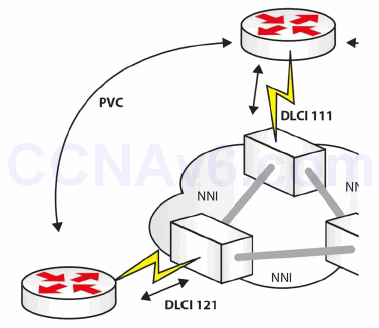
Figure 42.3 – A PVC
DLCI
The Data Link Connection Identifier (DLCI) is a locally significant number used to identify your connection to the Frame Relay switch, as illustrated in Figure 42.4 below. This number can be anything from 10 to 1007, inclusive.
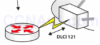
Figure 42.4 – DLCI Identifies Your Router to the Telco
Often, when troubleshooting Frame Relay links, the issue lies with either the customer or the service provider using the wrong DLCI number on their configuration.
When your DLCI is active, an end-to-end connection forms in the following order:
- Active DLCI sends Inverse ARP request
- DLCI waits for reply with network address
- Map created of remote router address
- DLCI status of Active/Inactive/Deleted
NNI
The Network-to-Network Interface (NNI) is the connection between Frame Relay switches.
Frame Relay Technology
Frame Relay is a Non-Broadcast Multi-Access (NBMA) technology. This means that you have to deal with address resolution issues, except for the situations in which you use Point-to-Point interfaces.
The local Layer 2 addresses in Frame Relay are called Data Link Connection Identifiers (DLCI) and this is only locally significant. For example, in a hub-and-spoke environment, the hub device should have a unique DLCI to communicate to each of its spokes.
When you inspect the Frame Relay PVC status on a Cisco device, you will see a status code defined by LMI that can be any one of the following:
- Active (everything is okay)
- Inactive (no problems on the local node but possible problems on the remote node)
- Deleted (problem in the service provider network)
As an example, Cisco devices offer three flavours of LMI:
- CISCO
- ANSI
- Q.933a
Cisco routers are configured to automatically try all three of these LMI types (starting with the CISCO LMI) and use the one that matches whatever the service provider is using, so this should not be of much concern in the design phase.
One of the most important aspects that needs to be considered in the design phase is the address resolution methodology used. If you are utilising Multipoint interfaces in your design (i.e., interfaces that can terminate multiple Layer 2 circuits), you need to find a way to provide the Layer 3 to Layer 2 resolution. As discussed previously, you have two options that can help you achieve this:
- Dynamically, utilising Inverse ARP
- Statically, via the frame-relay map static configuration command on Cisco devices
NOTE: In order to verify that the Layer 3 to Layer 2 resolution has succeeded, you can use the show frame-relay map command.
On a Multipoint interface, Inverse ARP would happen automatically. This functionality is enabled right after adding an IP address on an interface configured for Frame Relay. At that moment, requests start being sent out all of the circuits assigned to that specific interface for any supported protocol the interface is running.
The request process can be disabled with the no frame-relay inverse-arp command, but you can never design a network that will stop responding to requests. By design, Inverse ARP replies cannot be disabled, so the Frame Relay speaker will always attempt to assist somebody thatattempts to do a Layer 3 to Layer 2 resolution via the Frame Relay Inverse ARP.
The Inverse ARP behaviour in the Frame Relay design will automatically assist with Broadcasts through the replicated Unicast approach discussed before. When using Inverse ARP, Broadcast support exists by default.
If you connect two routers to the Frame Relay cloud using physical interfaces, this means that the specific interfaces are Multipoint from a Frame Relay perspective, because a physical Frame Relay interface by default is a Multipoint structure. Even though the connection between the two routers may appear to be Point-to-Point, it is a Frame Relay Multipoint connection.

Figure 42.5 – Frame Relay Multipoint Example
Because they use Multipoint interfaces, by default the two devices will handle the Layer 3 to Layer 2 resolution dynamically by using Inverse ARP. If you would like to design a solution in which Inverse ARP would not be used, you can turn off the dynamic mapping behaviour on each device and then configure static Frame Relay mappings.
Point-to-point configurations are the ideal choice when it comes to Layer 3 to Layer 2 resolution because this process does not occur when using such interface types. When configuring Point-to-Point Frame Relay, you would use Point-to-Point subinterfaces and these subinterfaces would not get the DLCI assignments from LMI, like in the Multipoint situation.
Another option would be to create subinterfaces and declaring them as Multipoint. These types of interfaces behave exactly like the physical Multipoint interfaces, so you need to decide on the resolution method to be used, either Inverse ARP or static mappings. A combination of these methods can be used, for example, by implementing Inverse ARP on one end of the connection and defining static maps on the other end.
The interface type settings and the selected Layer 3 to Layer 2 resolution method is only locally significant. This means that you can have all kinds of variations in your Frame Relay design, such as those listed in Table 42.1 below:
Table 42.1 – Variations in the Frame Relay Design

Partial-mesh designs and configurations will be the most challenging. This implies that Layer 2 circuits will not be provisioned between all endpoints involved in the Frame Relay environment.
In a hub-and-spoke environment, the spokes are not directly connected to each other, so this means that they cannot resolve each other via Inverse ARP. In order to solve these issues, you can do any of the following:
- Provide additional static mappings
- Configure Point-to-Point subinterfaces
- Design the hub-and-spoke infrastructure so that the Layer 3 routing design can solve the
resolution problems (e.g., by using the OSPF Point-to-Multipoint network type)
Frame Relay supports markings that can impact Quality of Service (QoS). For example, the Frame Relay header contains a DE (Discard Eligible) bit. With Frame Relay environments for QoS, packets can be marked with the DE bit and this informs the service provider that those specific packets are not very important and can be discarded in case of congestion. This behaviour will prioritise packets that do not have the DE bit set.
Other parameters that can be configured in the Frame Relay environment are Forward Explicit Congestion Notifications (FECNs) and Backwards Explicit Congestion Notifications (BECNs) which commonly crops up as an exam question. The Frame Relay equipment, if configured to do so, can notify devices of congestion and can cause the slowing down of the sending rates.
Configuring Frame Relay
Unfortunately, it can be somewhat tricky to configure Frame Relay, and this is because different network types require different commands. The reason for this is to overcome how network addresses resolve over the WAN and how routing protocols operate. The steps to configure Frame Relay are as follows:
- Set encapsulation
- Set LMI type (optional)
- Configure static/dynamic address mapping
- Address protocol-specific problems
You will not be expected to know how to configure a telco Frame Relay switch in the CCNA exam. You would only want to know how to do this if you are setting up your own Frame Relay connection on a home or remote lab.
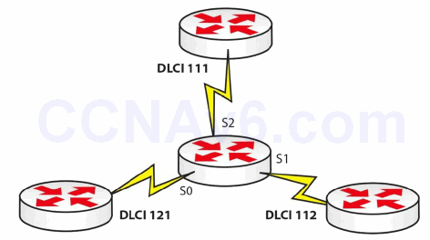
Figure 42.6 – Frame Relay Network
For the network topology above, you would configure the following on the Frame Relay switch in the middle. Please only use this information for reference, as you won’t need it for the exam:
Router#conf t
Router(config)#frame-relay switching
Router(config)#int s0
Router(config-if)#clock rate 64000
Router(config-if)#encapsulation frame-relay
Router(config-if)#frame-relay intf-type dce
Router(config-if)#frame-relay route 121 interface s1 112
Router(config-if)#frame-relay route 121 interface s2 111
Router(config-if)#no shut
Router(config-if)#int s1
Router(config-if)#clock rate 64000
Router(config-if)#encapsulation frame-relay
Router(config-if)#frame-relay intf-type dce
Router(config-if)#frame-relay route 112 interface s0 121
Router(config-if)#frame-relay route 112 interface s2 111
Router(config-if)#int s2
Router(config-if)#clock rate 64000
Router(config-if)#encapsulation frame-relay
Router(config-if)#frame-relay intf-type dce
Router(config-if)#frame-relay route 111 interface s0 121
Router(config-if)#frame-relay route 111 interface s1 112
Router(config-if)#no shut
Router#show frame-relay route
Troubleshooting Frame Relay
As stated earlier, often the telco gets the mapping information wrong when they map your DLCI to the wrong port or get the number wrong. You will need to prove that they are at fault before calling them or logging a ticket, using the following commands:
show frame-relay pvc show frame-relay lmi show frame-relay map debug frame-relay pvc debug frame-relay lmi
Frame Relay Errors
Annoyingly, in the exam they sometimes like to ask you about errors on the Frame Relay link, so here is what you need to know:
- BECN – Frames in the direction opposite of the frame transmission experienced congestion
- FECN – Congestion was experienced in the direction of the frame transmission PPP Operations
PPP is considered an Internet-friendly protocol due to the following factors:
- It supports data compression
- Authentication is built in (PAP and CHAP)
- Network Layer address negotiation
- Error detection
You can use PPP over several connection types, including the following:
- DSL
- ISDN
- Synchronous and asynchronous links
- HSSI
PPP can be broken down into the following Layer 2 sublayers:
- NCP – establishes Network Layer protocols (serves the Network Layer)
- LCP – establishes, authenticates, and tests link quality (serves the Physical Layer)
- HDLC – encapsulates datagrams over the link
Knowing the above may well come in handy during your CCNA exam!
Configuring PPP
PPP is very easy to configure, as shown in Figure 42.7 and the following output below. You can also add authentication, which will be demonstrated in a moment.

Figure 42.7 – A PPP Connection
R1#conf t
R1(config)#interface s0
R1(config-if)#ip add 192.168.1.1 255.255.255.0
R1(config-if)#clock rate 64000
R1(config-if)#encapsulation ppp
R1(config-if)#no shut
R2#conf t
R2(config)#interface s0
R2(config-if)#ip add 192.168.1.2 255.255.255.0
R2(config-if)#encapsulation ppp
R2(config-if)#no shut
PPP Authentication
PPP has built-in authentication in the form of Password Authentication Protocol (PAP) or Challenge Handshake Authentication Protocol (CHAP). PAP sends the passwords over the link in clear text, which poses a security risk, whereas CHAP sends a hashed value using MD5 security. Here is a CHAP configuration:

Figure 42.8 – PPP with CHAP
R1#conf t
R1(config)#username R2 password Cisco
R1(config)#interface s0
R1(config-if)#ip add 192.168.1.1 255.255.255.0
R1(config-if)#clock rate 64000
R1(config-if)#encapsulation ppp
R1(config-if)#ppp authentication chap
R1(config-if)#no shut
R2#conf t
R2(config)#username R1 password Cisco
R2(config)#interface s0
R2(config-if)#ip add 192.168.1.2 255.255.255.0
R2(config-if)#encapsulation ppp
R2(config-if)#ppp authentication chap
R2(config-if)#no shut
To configure PAP, you would replace the [chap] keyword in the configuration above with the [pap] keyword. You can also configure PPP to attempt authentication using CHAP, but if this isn’t successful, attempt with PAP. This is known as PPP fallback and here is the command:
R2(config-if)#ppp authentication chap pap
Troubleshooting PPP
Issue a show interface serial 0/0 command, or the relevant interface number, to display the IP address, interface status, and the encapsulation type, as illustrated in the output below:
RouterA#show interface Serial0/0

Serial0 is up, line protocol is up
  Hardware is HD64570
  Internet address is 192.168.1.1/30
  MTU 1500 bytes, BW 1544 Kbit, DLY 20000 usec,
  reliability 255/255, txload 1/255, rxload 1/255
  Encapsulation PPP, loopback not set
  Keepalive set (10 sec)
If you are using CHAP, then check to ensure that the username matches that of the router you are calling, and bear in mind that the hostnames are case sensitive. You troubleshoot PPP session establishment with the commands debug ppp authentication and debug ppp negotiation.
Section 42 Questions
- Frame Relay is based on which older protocol?
- What are the three types of LMIs available?
- An LMI is sent every _______ seconds, and every _______ message is a full status update.
- The DLCI number is only locally significant, so you could have a different one for the other end of your Frame Relay connection. True or false?
- Explain the difference between BECNs and FECNs.
- PPP does not include data compression or error detection. True or false?
- Name the PPP sublayers.
- Write out the command to configure CHAP with PPP.
- Which command will show you the encapsulation type on your Serial interface?
- _______ sends the passwords over the link in clear text, which poses a security risk, whereas _______ sends a hashed value using MD5 security.
Section 42 Answers
- The X.25 protocol.
- CISCO, ANSI, and Q933a.
- 10, sixth.
- True.
- Backward Explicit Congestion Notification (BECN): Frames in the direction opposite of the frame transmission experienced congestion; Forward Explicit Congestion Notification (FECN): Congestion was experienced in the direction of the frame transmission.
- False.
- NCP, LCP, and HDLC.
- ppp authentication chap.
- The show interface serial [number] command.
- PAP, CHAP.
Section 42 Labs
HDLC Lab
Topology

Purpose
Try your hand at WAN troubleshooting.
Walkthrough
No walkthrough for this lab. Configure the network above. Your WAN will work using HDLC automatically. Ping across the Serial link to ensure that it is working. Then, break the network in the following ways.
1. Change the encapsulation type on Router B to PPP (thus breaking the link at layer 2). Do this with the following configuration:
RouterB(config)#int Serial0/1/0
RouterB(config-if)#encapsulation ppp
%LINEPROTO-5-UPDOWN: Line protocol on Interface Serial0/1/0, changed state to down
RouterB(config-if)#
2. Issue a shut command on the Serial interface on Router A. Then issue a show ip interface brief command. You should see your interface up/down.
3. Take the clock rate off your DCE interface side. Then issue the show controllers serial x command. It should tell you there is no clock rate configured.
4. Change the subnet mask on the Router B side to 255.255.255.0. You can see the subnet mask with a show interface serial x command. If that command isn’t permitted in the exam, then issue a show run command.
5. Now fix all of the issues above. This is what you will have to do in the exam, and these are the most common issues. Please do test the commands you would enter if you were troubleshooting this issue to show you the IP address, encapsulation type, and clock rate.
6.
Frame Relay Lab
Topology

Purpose
Learn to configure basic Frame Relay.
Walkthrough
1. Configure the Frame Relay switch first. You will never have to do this in the CCNA exam. Also, add the IP addresses to the Serial interfaces on Routers A and B.
Router#conf t
Enter configuration commands, one per line. End with CNTL/Z.
Router#hostname FrameSwitch
FrameSwitch(config)#frame-relay switching
FrameSwitch(config)#int s1/0
FrameSwitch(config-if)#encap frame-relay
FrameSwitch(config-if)#frame-relay intf-type dce
FrameSwitch(config-if)#clock rate 64000
FrameSwitch(config-if)#frame-relay route 100 int s1/1 200
FrameSwitch(config-if)#no shut
*May 10 04:28:13.275: %LINK-3-UPDOWN: Interface Serial1/0, changed state to up
*May 10 04:28:29.275: %LINEPROTO-5-UPDOWN: Line protocol on Interface Serial1/0, changed
state to up
FrameSwitch(config-if)#int s1/1
FrameSwitch(config-if)#encap frame
FrameSwitch(config-if)#frame-relay intf-type dce
FrameSwitch(config-if)#clock rate 64000
FrameSwitch(config-if)#frame route 200 int s1/0 100
FrameSwitch(config-if)#no shut
FrameSwitch(config-if)#^Z
FrameSwitch#show frame route
Input Intf   Input Dlci   Output Intf     Output Dlci   Status
Serial1/0    100       Serial1/1      200     inactive
Serial1/1    200       Serial1/0      100     inactive
FrameSwitch#
2. Configure Frame Relay on Router A.
RouterA(config)#interface s0/1/0
RouterA(config-if)#encap frame-relay
RouterA(config-if)#frame-relay interface-dlci 100
RouterA(config-if)#no shut
3. Copy these commands on Router B, but your DLCI number is 200.
4. Ping across the Frame Relay link to test whether it has come up.
RouterB#ping 192.168.1.1
Type escape sequence to abort.
Sending 5, 100-byte ICMP Echos to 192.168.1.1, timeout is 2 seconds:
!!!!!
Success rate is 100 percent (5/5), round-trip min/avg/max = 12/17/20 ms
RouterB#
5. Check the Frame Relay PVC and mapping.
RouterB#show frame-relay pvc
PVC Statistics for interface Serial1/1 (Frame Relay DTE)
              Active     Inactive      Deleted       Static
  Local          1            0            0            0
  Switched       0            0            0            0
  Unused         0            0            0            0
DLCI = 200, DLCI USAGE = LOCAL, PVC STATUS = ACTIVE, INTERFACE = Serial1/1
  input pkts 1            output pkts 1            in bytes 34
  out bytes 34            dropped pkts 0           in pkts dropped 0
  out pkts dropped 0                out bytes dropped 0
  in FECN pkts 0           in BECN pkts 0           out FECN pkts 0
  out BECN pkts 0          in DE pkts 0             out DE pkts 0
  out bcast pkts 1         out bcast bytes 34
  5 minute input rate 0 bits/sec, 0 packets/sec
  5 minute output rate 0 bits/sec, 0 packets/sec
  pvc create time 00:00:26, last time pvc status changed 00:00:26
RouterB#
RouterB#show frame map
Serial1/1 (up): ip 192.168.1.1 dlci 200(0xC8,0x3080), dynamic,
              broadcast, status defined, active
RouterB#
6. Debug Frame Relay LMI exchanges. When you see the status 0x2 tag, issue an undebug all command to turn off debugs.
Router3#debug frame-relay lmi
Frame Relay LMI debugging is on
Displaying all Frame Relay LMI data
Router3#
*May 10 04:42:48.311: Serial1/1(out): StEnq, myseq 24, yourseen 23, DTE up
*May 10 04:42:48.311: datagramstart = 0xF1A6FCC4, datagramsize = 13
*May 10 04:42:48.311: FR encap = 0xFCF10309
*May 10 04:42:48.311: 00 75 01 01 01 03 02 18 17
*May 10 04:42:48.311:
*May 10 04:42:48.319: Serial1/1(in): Status, myseq 24, pak size 13
*May 10 04:42:48.319: RT IE 1, length 1, type 1
*May 10 04:42:48.319: KA IE 3, length 2, yourseq 24, myseq 24
Router3#
*May 10 04:42:58.311: Serial1/1(out): StEnq, myseq 25, yourseen 24, DTE up
*May 10 04:42:58.311: datagramstart = 0xF1A73AFC, datagramsize = 13
*May 10 04:42:58.311: FR encap = 0xFCF10309
*May 10 04:42:58.311: 00 75 01 01 00 03 02 19 18
*May 10 04:42:58.311:
*May 10 04:42:58.319: Serial1/1(in): Status, myseq 25, pak size 21
*May 10 04:42:58.319: RT IE 1, length 1, type 0
*May 10 04:42:58.319: KA IE 3, length 2, yourseq 25, myseq 25
*May 10 04:42:58.319: PVC IE 0x7, length 0x6, dlci 200, status 0x2, bw 0
Router3#un all
Point-to-Point Protocol Lab
Topology

Purpose
Learn how to configure PPP and CHAP.
Walkthrough
1. Configure IP addresses and hostnames as per the topology above.
2. Set the encapsulation on each side to PPP. Here is the command for Router A:
RouterA(config)#interface s0/1/0
RouterA(config-if)#encapsulation ppp
3. Set CHAP on each router. You will set the hostname of the opposite router and the password cisco.
RouterA(config)#username RouterB password cisco
RouterA(config-if)#ppp authentication chap
RouterA(config-if)#exit
RouterB(config)#username RouterA password cisco
RouterB(config-if)#ppp authentication chap
RouterB(config-if)#exit
4. Ping across the link to ensure it is up.
RouterB#ping 10.0.0.1
Type escape sequence to abort.
Sending 5, 100-byte ICMP Echos to 10.0.0.1, timeout is 2 seconds:
!!!!!
Success rate is 100 percent (5/5), round-trip min/avg/max = 31/31/32 ms
RouterB#
5. Break the connection by changing the hostname on Router A to Router C. You will also want to turn on PPP debugs and shut/no shut the interface to open negotiation again. You will have to be quick to type undebug all. If you are at the interface prompt, then type do undebug all.
RouterA#conf t
Enter configuration commands, one per line. End with CNTL/Z.
RouterA(config)#hostname RouterC
RouterC(config)#exit
RouterC#
RouterC#debug ppp neg
PPP protocol negotiation debugging is on
RouterC#debug ppp auth
RouterC#config t
RouterC(config)#int s0/1/0
RouterC(config-if)#shut
Serial0/1/0 LCP: State is Open
Serial0/1/0 PPP: Phase is AUTHENTICATING
Serial0/1/0 IPCP: O CONFREQ [Closed] id 1 len 10 ← Router won’t authenticate
RouterC(config-if)#do undebug all
RouterC#sh int s0/1/0
Serial0/1/0 is up, line protocol is down (disabled)
