6.0 – Introduction
6.0.1 – Welcome
6.0.1.1 – Chapter 6: Applied Networking
Virtually all computers and mobile devices today are connected to some type of network and to the Internet. This means that configuring and troubleshooting computer networks is now a critical skill for IT professionals. This chapter focuses on applied networking with in-depth discussion on the format and architecture of media access control (MAC) addresses and Internet protocol (IP) addresses, both IPv4 and IPv6, that are used to connect computers to a network. Examples of how to configure static and dynamic addressing on computers are included. Also covered in this chapter is the configuration of both wired and wireless networks, firewalls, and IoT devices.
You will learn how to configure network interface cards (NICs), connect devices to a wireless router, and configure a wireless router for network connectivity. You will learn how to configure wireless network basic wireless settings, Network Address Translation (NAT), firewall settings, and Quality of Service (QoS). You will also learn about firewalls, Internet of Things (IoT) devices, and network troubleshooting. At the end of the chapter you will learn the six step troubleshooting process and common problems and solutions for computer networks.
Your networking skills should include the ability to configure wireless networks so that hosts can communicate, configure firewalls to filter traffic, verify network connectivity, and solve network connectivity problems. There are three labs included in this chapter where you will build these skills. In these labs you will configure basic settings on a wireless router and connect a PC to the wireless network, configure firewall settings to implement MAC address filtering, a DMZ, and single port forwarding, and finally, diagnose and solve network problems.
6.1 – Device to Network Connection
6.1.1 – Network Addressing
6.1.1.1 – Video Explanation – MAC Addressing
Click Play in the figure to view a video about Media Access Control (MAC) addresses.
Click here to read the transcript of this video.
6.1.1.2 – Video Explanation – IPv4 Addressing
Click Play in the figure to view a video about Internet Protocol (IP) v4 addressing.
Click here to read the transcript of this video.
6.1.1.3 – Video Explanation – IPv6 Addressing
Click Play in the figure to view a video about IPv6 addressing.
Click here to read the transcript of this video.
6.1.1.4 – Two Network Addresses
Your fingerprint and mailing address are two ways to identify you and locate you. Your fingerprint usually does not change. Your fingerprint can be used to uniquely identify you, wherever your location. Your mailing address is different. It is your location. Unlike your fingerprint, your mailing address can change.

A fingerprint is like a MAC address.
Devices that are attached to a network have two addresses that are similar to your fingerprint and mailing address, as shown in the figure. These two types of addresses are the Media Access Control (MAC) address and the Internet Protocol (IP) address.

A mailing address is like an IP address
The MAC address is hard-coded onto the Ethernet or wireless network interface card (NIC) by the manufacturer. The address stays with the device regardless of what network the device is connected to. A MAC address is 48 bits and can be represented in one of the three hexadecimal formats shown in Figure 2.

MAC Address Format
IP addressing is assigned by network administrators based on the location within the network. When a device moves from one network to another, its IP address will most likely change. An IP version 4 (IPv4) address is 32 bits and represented in dotted decimal notation. An IP version 6 (IPv6) address is 128 bits and is represented in hexadecimal format, as shown in Figure 3.

IPv4 Address Format

IPv6 Address Format
Figure 4 shows a topology with two local area networks (LANs). This topology demonstrates that MAC addresses do not change when a device is moved. But IP addresses do change. The laptop was moved to LAN 2. Notice that the laptop’s MAC address did not change, but its IP addresses did change.
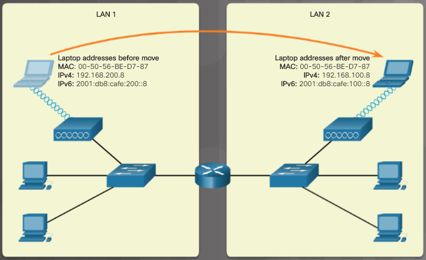
A topology with two local area networks (LANs)
Note: Converting between decimal, binary, and hexadecimal numbering systems is beyond the scope of this course. Search the internet to learn more about these numbering systems.
6.1.1.5 – Displaying the Addresses
Today, your computer probably has an IPv4 and an IPv6 address, as shown for the laptop in the figure. In the early 1990s, there was a concern about running out of IPv4 network addresses. The Internet Engineering Task Force (IETF) began to look for a replacement. This led to the development of IPv6. Currently, IPv6 is operating alongside IPv4 and is beginning to replace it.
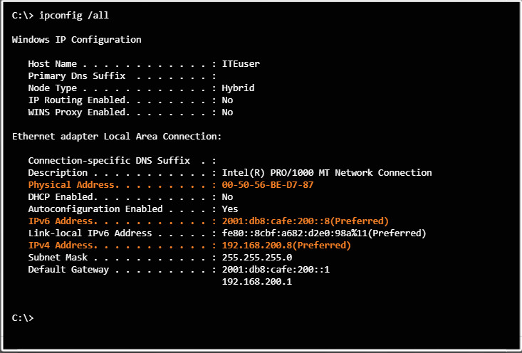
The Figure shows output for the command ipconfig /all on the laptop. The output is highlighted to show the MAC address and two IP addresses.
Note: Windows OS calls the NIC an Ethernet adapter and the MAC address a physical address.
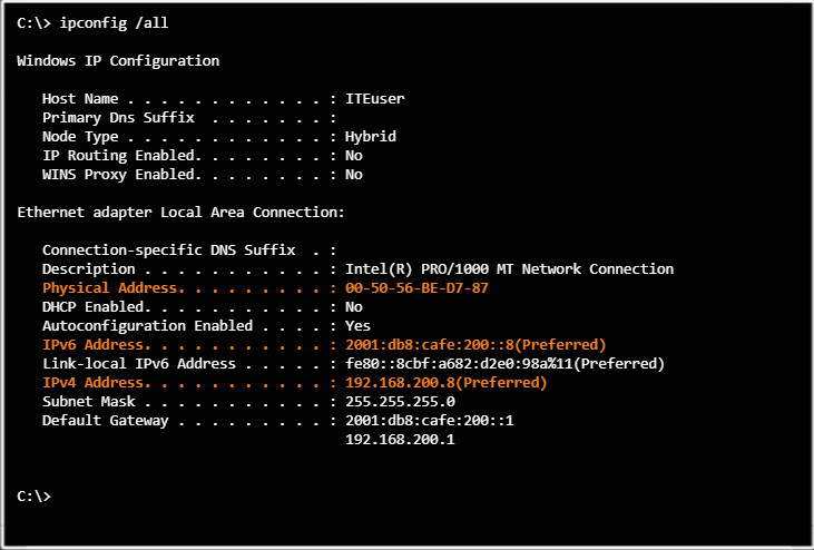
Laptop Addressing Information
6.1.1.6 – IPv4 Address Format
When you manually configure a device with an IPv4 address, you enter it in dotted decimal format, as shown for a Windows computer in Figure 1. Each number separated by a period is called an octet because it represents 8 bits. Therefore, the 32-bit address 192.168.200.8 has four octets.
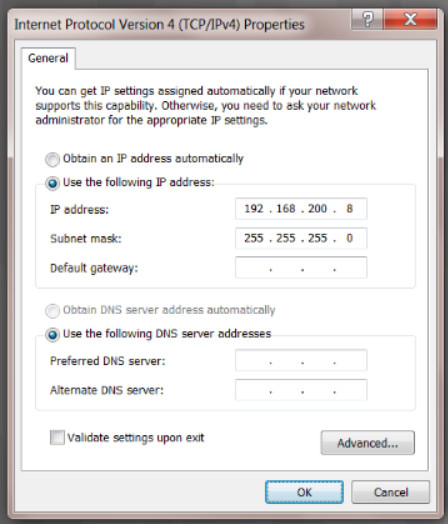
Figure 1 – IPv4 address
An IPv4 address is composed of two parts. The first part identifies the network. The second part identifies this device on the network. The subnet mask is used by the device to determine the network. For example, the computer in Figure 1 uses the subnet mask 255.255.255.0 to determine that the IPv4 address 192.168.200.8 belongs to the 192.168.200.0 network. The .8 portion is this device’s unique host portion on the 192.168.200 network. Any other device with that same 192.168.200 prefix will be on the same network but have a different value for the host portion. Devices with a different prefix will be on a different network.
To see this at the binary level, you can convert the 32-bit IPv4 address and subnet mask to their binary equivalents, as shown in Figure 2. A one bit in the subnet mask means that bit is part of the network portion. So, the first 24 bits of the 192.168.200.8 address are network bits. The last 8 bits are host bits.
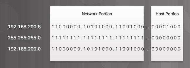
The Role of the Subnet Mask
When your device prepares data to send out on the network, it must first determine whether to send data directly to the intended receiver or to a router. It will send it directly to the receiver if the receiver is on the same network. Otherwise, it will send the data to a router. A router then uses the network portion of the IP address to route traffic between different networks.
For example, if the Windows computer in Figure 1 has data to send to a host at 192.168.200.25, it sends the data directly to that host because it has the same prefix of 192.168.200. If the destination’s IPv4 address is 192.168.201.25, then the Window’s computer will send the data to a router.
6.1.1.7 – IPv6 Address Formats
IPv6 overcomes the address space limitations of IPv4. The 32-bit IPv4 address space provides approximately 4,294,967,296 unique addresses. The 128-bit IPv6 address space provides 340,282,366,920,938,463,463,374,607,431,768,211,456 addresses, or 340 undecillion addresses.
The 128 bits of an IPv6 addresses are written as a string of hexadecimal values, with letters expressed in lowercase. Every 4 bits is represented by a single hexadecimal digit for a total of 32 hexadecimal values. The examples shown in Figure 1 are fully expanded IPv6 addresses. Two rules help reduce the number of digits needed to represent an IPv6 address.

Fully Expanded IPv6 Address Examples
Rule 1 – Omit Leading Os
The first rule to help reduce the notation of IPv6 addresses is to omit any leading 0s (zeros) in any 16-bit section. For example, in Figure 1:
- 0db8 can be represented as db8, in the first IPv6 address
- 0123 can be represented as 123, in the second IPv6 address
- 0001 can be represented as 1, in the third IPv6 address
Note: IPv6 addresses must be represented in lowercase letters, but you may often see them as uppercase.
Rule 2 – Omit All 0 Segments
The second rule to help reduce the notation of IPv6 addresses is that a double colon (::) can replace any group of consecutive zeros. The double colon (::) can only be used once within an address, otherwise there would be more than one possible resulting address.
Figures 2 to 4 show examples of how to use the two rules to compress the IPv6 addresses shown in Figure 1.

Compressing an IPv6 Address – Figure 1

Compressing an IPv6 Address – Figure 2

Compressing an IPv6 Address – Figure 3
6.1.1.8 – Static Addressing
In a small network, you can manually configure each device with proper IP addressing. You would assign a unique IP address to each host within the same network. This is known as static IP addressing.
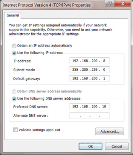
Assigning Static IPv4 Addressing
On a Windows computer, as shown in Figure 1, you can assign the following IPv4 address configuration information to a host:
- IP address – identifies this device on the network
- Subnet mask – is used to identify the network on which this device is connected
- Default gateway – identifies the router that this device uses to access the internet or another network
- Optional values – such as the preferred Domain Name System (DNS) server address and the alternate DNS server address
Similar configuration information for IPv6 addressing is shown in Figure 2.
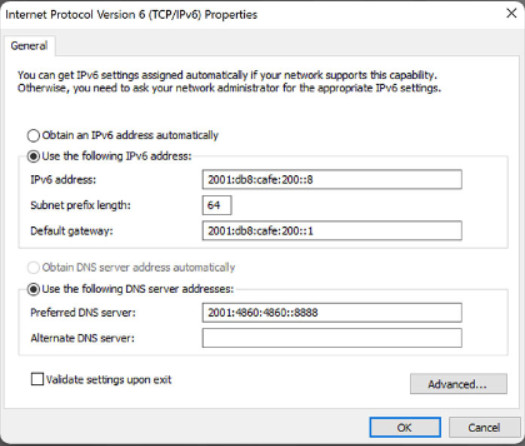
Internet Protocol Version 6 Properties
6.1.1.9 – Dynamic Addressing
Rather than manually configure every device, you can take advantage of implementing a Dynamic Host Configuration Protocol (DHCP) server. A DHCP server automatically assigns IP addresses, which simplifies the addressing process. Automatically configuring some of the IP addressing parameters also reduces the possibility of assigning duplicate or invalid IP addresses.
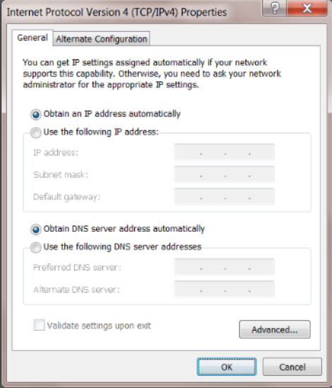
Configuring DHCP Addressing
By default, most host devices are configured to request IP addressing from a DHCP server. The default setting for a Windows computer is shown in the figure. When a computer is set to obtain an IP address automatically, all other IP addressing configuration boxes are not available. This process is the same for a wired or wireless NIC.
A DHCP server can automatically assign the following IPv4 address configuration information to a host:
- IPv4 address
- Subnet mask
- Default gateway
- Optional values, such as a DNS server address
DHCP is also available for automatically assigning IPv6 addressing information.
Note: The steps to configure a Windows computer is beyond the scope of this topic.
6.1.1.10 – Link-local IPv4 and IPv6 Addresses
Link-local addresses for IPv4 and IPv6 are used by a device to communicate with other computers connected to the same network within the same IP address range. The major difference between IPv4 and IPv6 is the following:
- An IPv4 device uses the link-local address if the device cannot obtain an IPv4 address.
- An IPv6 device must always be dynamically or manually configured with a link-local IPv6 address.
IPv4 Link-Local Address
If your Windows computer cannot communicate with a DHCP server to obtain an IPv4 address, then Windows automatically assigns an Automatic Private IP Addressing (APIPA) address. This link-local address is in the range of 169.254.0.0 to 169.254.255.255.
IPv6 Link-Local Address
Like IPv4, the IPv6 link-local address enables your device to communicate with other IPv6-enabled devices on the same network and only on that network. Unlike IPv4, every IPv6 enabled device is required to have a link-local address. IPv6 link-local addresses are in the range of fe80:: to febf::. For example, in the figure, the links to other networks are down (not connected) as notate by the red Xs. However, all the devices on the LAN can still use link-local IPv6 addresses to communicate with each other.
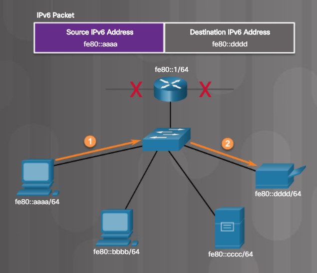
IPv6 Link-Local Communications
Note: Unlike IPv4 link-local addresses, IPv6 link-local addresses are used in a variety of processes including network discovery protocols and routing protocols. This is beyond the scope of this course.
6.1.1.11 – Check Your Understanding – Network Addressing
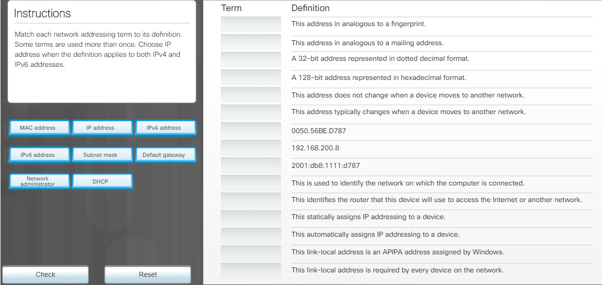
6.1.1.11 – Check Your Understanding – Network Addressing
6.1.2 – Configure a NIC
6.1.2.1 – Packet Tracer – Add Computers to an Existing Network
In this Packet Tracer activity, you will configure the computers to use DHCP, configure static addressing, use ipconfig to retrieve host IPv4 information, and use ping to verify connectivity.
Packet Tracer – Add Computers to an Existing Network Instructions
Packet Tracer – Add Computers to an Existing Network PKA
6.1.2.2 – Network Design
As a computer technician, you must be able to support the networking needs of your customers. Therefore, you must be familiar with:
- Network components – Includes wired and wireless network interface cards (NIC) and network devices such as switches, wireless access points (APs), routers, multipurpose devices, and more.
- Network design – Involves knowing how networks are interconnected to support the needs of a business. For instance, the needs of a small business will differ greatly from the needs of a large business.
Consider a small business with 10 employees. The business has contracted you to connect their users. As shown in the figure, a home or small office wireless router could be used for such a small number of users. These routers are multiple purpose and typically provide router, switch, firewall, and access point capabilities. In addition, these wireless routers often provide a variety of other services including DHCP.
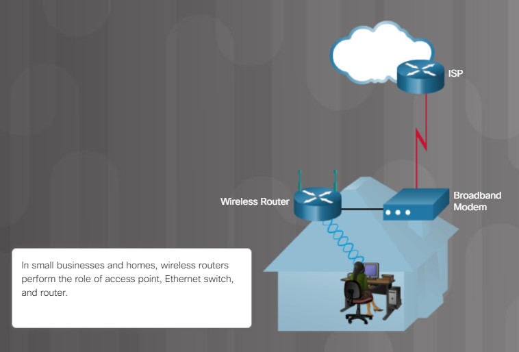
Typical Home Network
If the business was much larger, then you would not use a wireless router. Instead, you would consult with a network architect to design a network of dedicated switches, access points (AP), firewall appliances, and routers.
Regardless of network design, you must know how to install network cards, connect wired and wireless devices, and configure basic network equipment.
Note: This chapter will focus on connecting and configuring a small office or home wireless router. The configurations will be demonstrated using Packet Tracer. However, the same functionality and similar graphical user interface (GUI) elements exist in all wireless routers. You can purchase a variety of low-cost wireless routers online and from consumer electronic stores. Search the internet for “wireless router reviews” to research current recommendations.
6.1.2.3 – Selecting a NIC
A NIC is required to connect to the network. As shown in Figure 1, there are different types of NICs. Ethernet NICs are used to connect to Ethernet networks and wireless NICs are used to connect to 802.11 wireless networks. Most NICs in desktop computers are integrated into the motherboard or connected to an expansion slot. NICs are also available in a USB form factor.
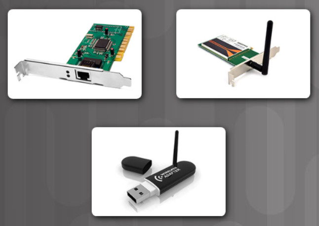
Types of NICs
Many computers purchased today come with a wired and wireless network interface integrated on the motherboard.
6.1.2.4 – Installing and Updating a NIC
Follow the steps to install adapter cards if you are installing a NIC inside the computer. A wireless NIC for a desktop device has an external antenna connected to the back of the card or attached with a cable so that it can be positioned for the best signal reception. You must connect and position the antenna.
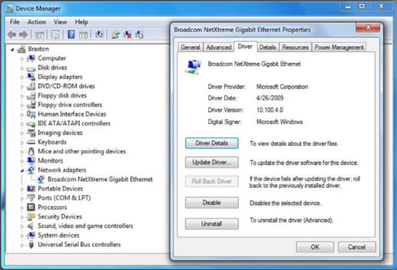
NIC Driver Management
Sometimes a manufacturer publishes new driver software for a NIC. A new driver might enhance the functionality of the NIC, or it might be needed for operating system compatibility. The latest drivers for all supported operating systems are available for download from the manufacturer’s website.
When installing a new driver, disable virus protection software to ensure that the driver installs correctly. Some virus scanners detect a driver update as a possible virus attack. Install only one driver at a time; otherwise, some updating processes might conflict. A best practice is to close all applications that are running so that they are not using any files associated with the driver update.
Note: An example of Windows Device Manager and the place to update a NIC’s driver is shown in the figure. However, details of how to update drivers for specific devices and operating systems is beyond the scope of this topic.
6.1.2.5 – Configure a NIC
After the NIC driver is installed, the IP address settings must be configured. For Windows computers, IP addressing is dynamic by default. After you physically connect a Windows computer to the network, it will automatically send out a request for IPv4 addressing the DHCP server. If a DHCP server is available, the computer will receive a message will all its IPv4 addressing information.
Note: Dynamic addressing for IPv6 can also use DHCP but is beyond the scope of this course.
This dynamic, default behavior is also typically for smartphones, tablets, gaming consoles, and other end-user devices. Static configuration is normally the job of a network administrator. However, you should be familiar with how to access the IP addressing configuration for any device you are asked to manage.
To find IP addressing configuration information, search the internet for “IP address configuration for device” where “device” is replaced with your device, such as “iPhone”. For example, Figure 1 shows the dialog box for viewing and changing a Windows computer’s IPv6 configuration. Figure 2 shows the setting screens for automatic and manual IPv4 configuration on an iPhone.
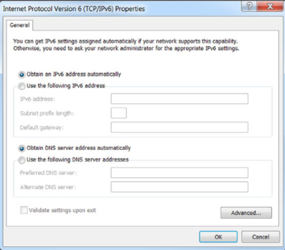
iPhone Automatic and Manual IPv4 Address Settings
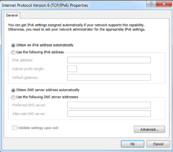
iPhone IP Address Settings
6.1.2.6 – ICMP
Internet Control Message Protocol (ICMP) is used by devices on a network to send control and error messages. There are several different uses for ICMP, such as announcing network errors, announcing network congestion, and troubleshooting.
Ping is commonly used to test connections between computers. To see a list of options that you can use with the ping command, type ping /? in the Command Prompt window, as shown in Figure 1.
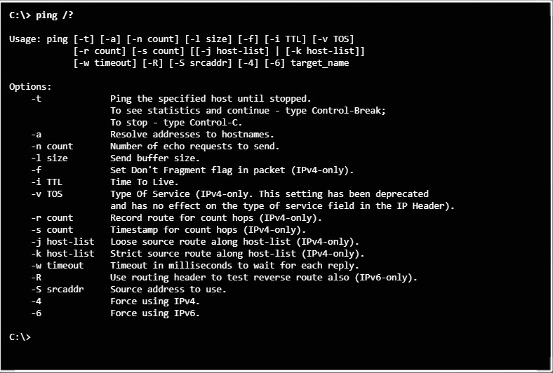
Testing Connectivity with Ping
Ping works by sending an ICMP echo request to the IP address you entered. If the IP address is accessible, the receiving device then sends back an ICMP echo reply message to confirm connectivity.
You can also use the ping command to test connectivity to a website by entering the website’s domain name. For example, if you enter ping cisco.com
your computer will first use DNS to find the IP address and then send the ICMP echo request to that IP address, as shown in Figure 2.
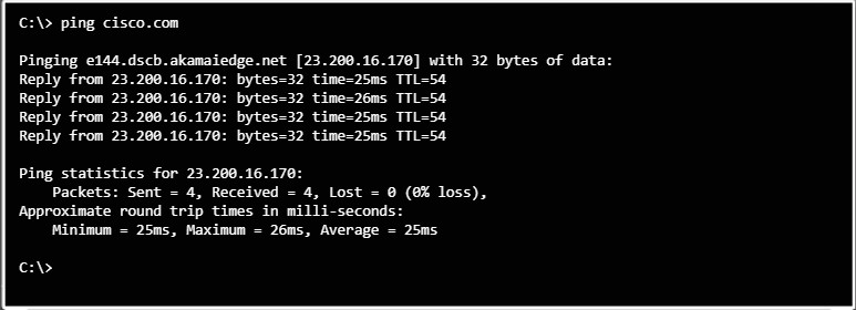
Testing Connectivity with Ping
6.1.2.7 – Lab – Configure a NIC to Use DHCP in Windows
In this lab, you will configure an Ethernet NIC to use DHCP to obtain an IP address and test connectivity between two computers.
6.1.2.7 Lab – Configure a NIC to Use DHCP in Windows
6.1.3 – Configure a Wired and Wireless Network
6.1.3.1 – Video Explanation – Configure a Wired and Wireless Network
Click Play in the figure to view a demonstration of how to configure a wired and wireless network.
Click here to read the transcript of this video.
6.1.3.2 – Connecting Wired Devices to the Internet
The steps to connect a wired device to the internet in a home or small office are as follows:
Step 1: Connect a network cable to the device.
To connect to a wired network, attach an Ethernet cable to the NIC port, as shown in Figure 1.
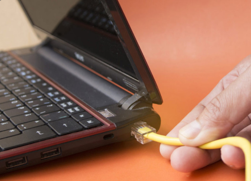
Step 1: Connect a network cable to the device.
Step 2: Connect the device to a switch port.
Connect the other end of the cable to an Ethernet port on the wireless router, such as one of the four yellow switch ports shown in Figure 2. In a SOHO network, the laptop would most likely connect to a wall jack which in turn connects to a network switch.
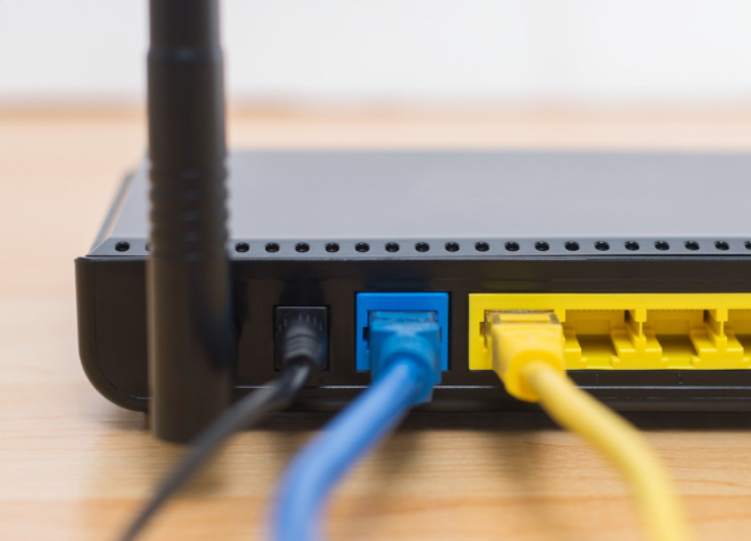
Step 2: Connect the device to a switch port.
Step 3: Connect a network cable to the wireless router internet port.
On the wireless router, connect an Ethernet cable to the port labeled Internet (blue port in Figure 2). This port might also be labeled WAN.
Step 4: Connect the wireless router to the modem.
The blue port in Figure 2 is an Ethernet port that is used to connect the router to a service provider device such as a DSL or cable modem in Figure 3.
Step 5: Connect to the service provider’s network.
The modem is then connected to the service provider’s network, as shown in Figure 3.
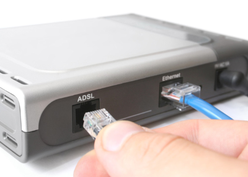
Step 5: Connect to the service provider’s network.
Note: A separate modem isn’t necessary if the wireless router is a router/modem combination.
Step 6: Power all devices and verify physical connections.
Turn on the broadband modem and plug in the power cord to the router. After the modem establishes a connection to the ISP, it will begin communicating with the router. The laptop, router, and modem LEDs will light up, indicating communication. The modem enables the router to receive the network information necessary to gain access to the internet from the ISP. This information includes public IPv4 addresses, subnet mask, and DNS server addresses. With the depletion of public IPv4 addresses, many ISPs are also providing IPv6 addressing information as well.
Figure 4 shows a topology depicting the physical connection of a wired laptop in the small office or home network.
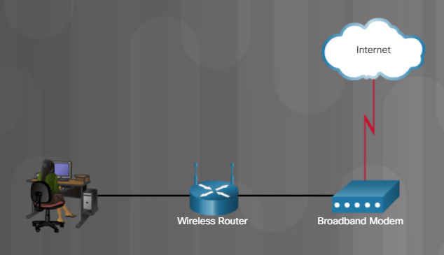
Small Office or Home Wired Network
Note: Cable or DSL modem configuration is usually done by the service provider’s representative either on-site or remotely through a walkthrough with you on the phone. If you buy the modem, it will come with documentation for how to connect it to your service provider which will most likely include contacting your service provider for more information.
6.1.3.3 – Logging in to the Router
Most home and small office wireless routers are ready for service out of the box. They preconfigured to be connected to the network and provide services. For example, the wireless router uses DHCP to automatically provide addressing information to connected devices. However, wireless router default IP addresses, usernames, and passwords can easily be found on the internet. Just enter the search phrase “default wireless router IP address” or “default wireless router passwords” to see a listing of many websites that provide this information. Therefore, your first priority should be to change these defaults for security reasons.
6.1.3.3 – Logging in to the Router
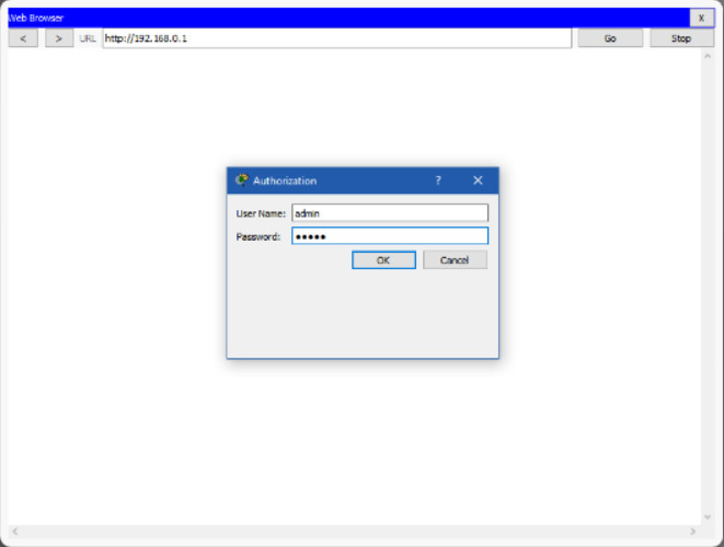
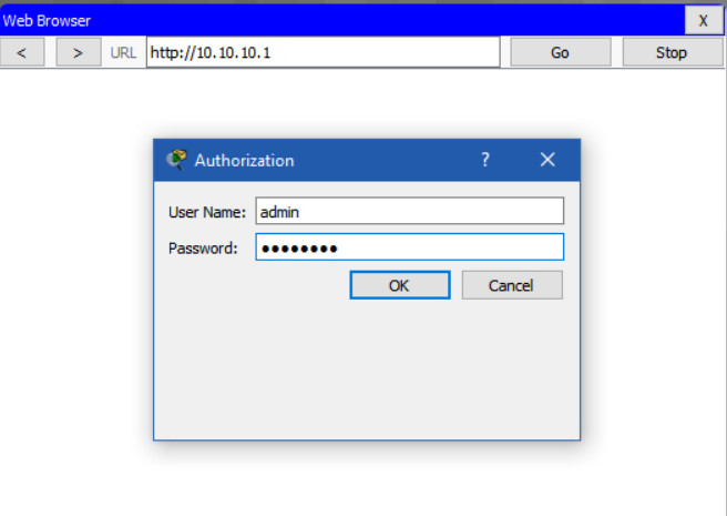
To gain access to the wireless router’s configuration GUI, open a web browser. In the address field, enter the default IP address for your wireless router. The default IP address can be found in the documentation that came with the wireless router or you can search the internet. The figure shows the IPv4 address 192.168.0.1, which is a common default for many manufacturers. A security window prompts for authorization to access the router GUI. The word admin is commonly used as the default username and password. Again, check your wireless router’s documentation or search the internet.
6.1.3.4 – Basic Network Setup
Instructions
Click each step below for more information and an example GUI.
After logging in, a GUI opens. The GUI will have tabs or menus to help you navigate to various router configuration tasks. It is often necessary to save the settings changed in one window before proceeding to another window. At this point, it is a best practice to make changes to the default settings.
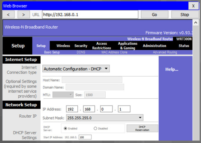
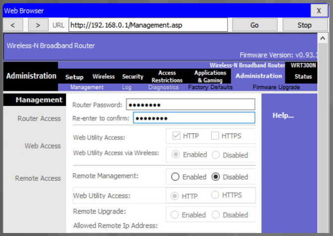
To change the default login password, find the administration portion of the router’s GUI. In this example, the Administration tab was selected. This is where the router password can be changed. On some devices, such as the one in the example, you can only change the password. The username remains admin or whatever the default username is for the router you are configuring.
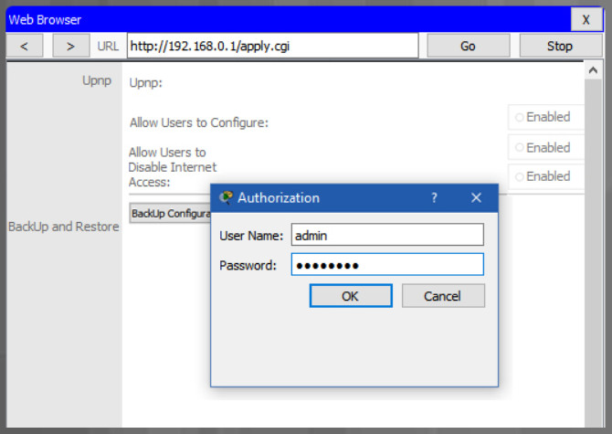
After you save the new password, the wireless router will request authorization again. Enter the username and new password, as shown in the example.
Change the default router IPv4 address. It is a best practice to use private IPv4 addressing inside your network. The IPv4 address 10.10.10.1 is used in the example but it could be any private IPv4 address you choose.
Search the internet for “private ip addressing” to learn more.
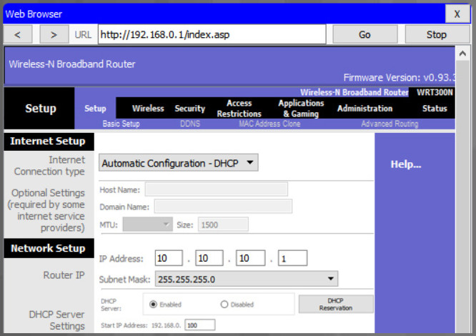
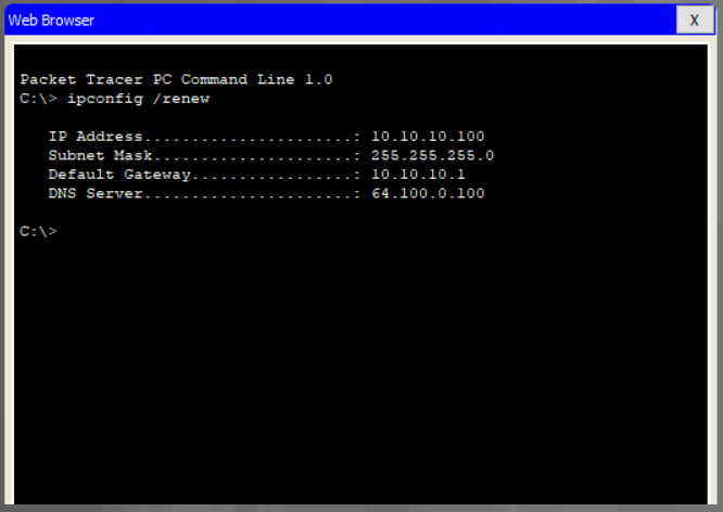
When you click save, you will temporarily lose access to the wireless router. Open a command window and renew your IP address with the ipconfig /renew command, as shown in the example.
Enter the router’s new IP address to regain access to the router configuration GUI, as shown in the example. You are now ready to continue configuring the router for wireless access.
6.1.3.5 – Basic Wireless Settings
Instructions
Click each step below for more information and an example GUI.
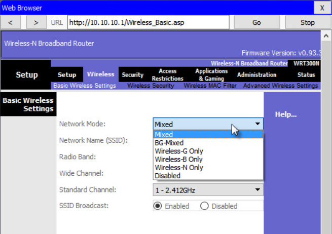
Out of the box, a wireless router provides wireless access to devices using a default wireless network name and password. The network name is called the Service Set Identified (SSID). Locate the basic wireless settings for your router to change these defaults, as shown in the example.
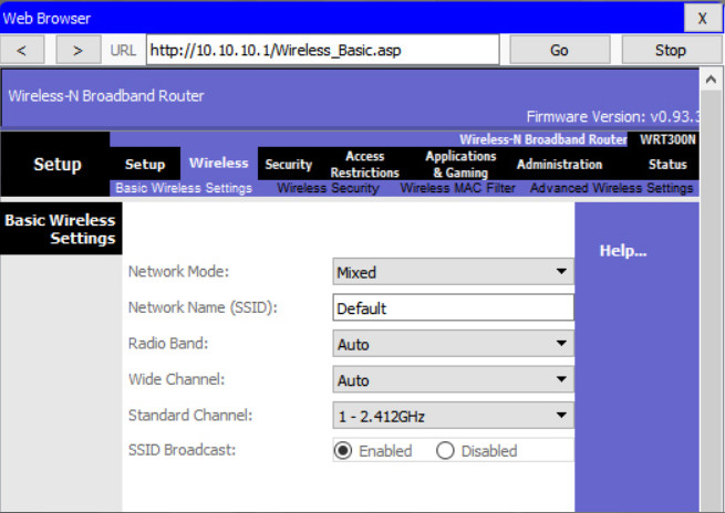
Some wireless routers allow you to select which 802.11 standard to implement. The example shows that “Mixed” has been selected. This means wireless devices connecting to the wireless router can have a variety of wireless NICs installed. Today’s wireless routers configured for mixed mode most likely support 802.11a, 802.11n, and 802.11ac NICs.
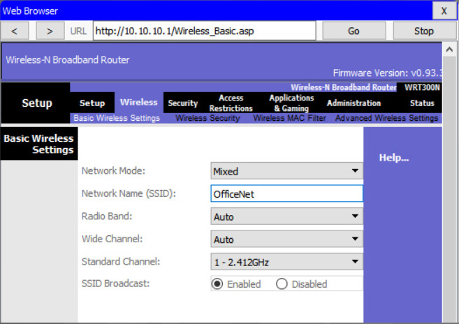
Assign an SSID to the wireless LAN (WLAN). OfficeNet is used in the example. The wireless router announces its presence by sending broadcasts advertising its SSID. This allows wireless hosts to automatically discover the name of the wireless network. If the SSID broadcast is disabled, you must manually enter the SSID on each wireless device that connects to the WLAN.
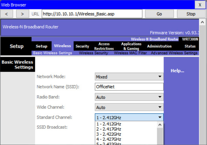
Devices configured with the same channel within the 2.4GHz band may overlap and cause distortion, slowing down the wireless performance and potentially break network connections. The solution to avoid interference is to configure non-overlapping channels on the wireless routers and access points that are near to each other. Specifically, channels 1, 6, and 11 are non-overlapping. In the example, the wireless router is configured to use channel 6.
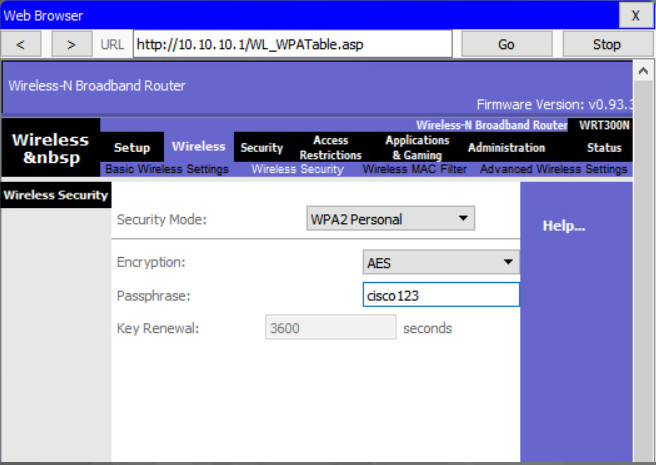
Out of the box, a wireless router may have no WLAN security configured. In the example, the personal version of Wi-Fi Protected Access version 2 (WPA2 Personal) is selected. WPA2 with Advanced Encryption Standard (AES) encryption is currently the strongest security mode.
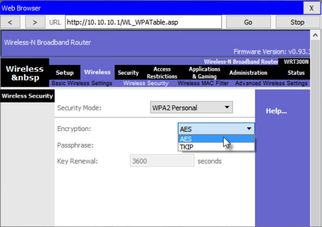
WPA2 personal uses a passphrase to authenticate wireless clients. WPA2 personal is easier to use in a small office or home environment because it does not require an authentication server. Larger organizations implement WPA2 enterprise and require wireless clients to authenticate with a username and password.
6.1.3.6 – Configure a Wireless Mesh Network
In a small office or home network, one wireless router may suffice to provide wireless access to all the clients. However, if you want to extend the range beyond approximately 45 meters indoors and 90 meters outdoors, you can add wireless access points. As shown in the wireless mesh network in the figure, two access points are configured with the same WLAN settings from our previous example. Notice that the channels selected are 1 and 11 so that the access points do not interfere with channel 6 configured previously on the wireless router.
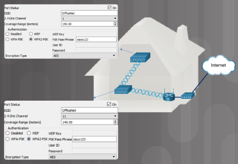
Wireless Mesh Network in a Home
Extending a WLAN in a small office or home has become increasingly easier. Manufacturers have made creating a wireless mesh network (WMN) simple through smartphone apps. You buy the system, disperse the access points, plug them in, download the app, and configure your WMN in a few steps. Search the internet for “best wi-fi mesh network system” to find reviews of current offerings.
6.1.3.7 – NAT for IPv4
On a wireless router, if you look for a page like the Status page shown in the figure, you will find the IPv4 addressing information that the router uses to send data to the internet. Notice that the IPv4 address is 209.165.201.11 is a different network than the 10.10.10.1 address assigned to the router’s LAN interface. All the devices on the router’s LAN will get assigned addresses with the 10.10.10 prefix.
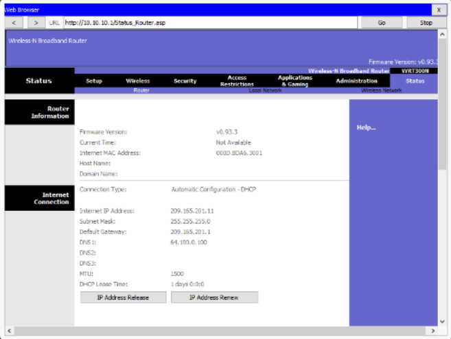
NAT for IPv4
The 209.165.201.11 IPv4 address is publicly routable on the internet. Any address with the 10 in the first octet is a private IPv4 address and cannot be routed on the internet. Therefore, the router will use a process called Network Address Translation (NAT) to convert private IPv4 addresses to Internet-routable IPv4 addresses. With NAT, a private (local) source IPv4 address is translated to a public (global) address. The process is reversed for incoming packets. The router is able to translate many internal IPv4 addresses into public addresses, by using NAT.
Some ISPs use private addressing to connect to customer devices. However, eventually, your traffic will leave the provider’s network and be routed on the internet. To see the IP addresses for your devices, search the internet for “what is my IP address.” Do this for other devices on the same network and you will see that they all share the same public IPv4 address. NAT makes this possible by tracking the source port numbers for every session established by a device. If your ISP has IPv6 enabled, you will see a unique IPv6 address for each device.
6.1.3.8 – Quality of Service
Many home and small office routers have an option for configuring Quality of Service (QoS). By configuring QoS, you can guarantee that certain traffic types, such as voice and video, are prioritized over traffic that is not as time-sensitive, such as email and web browsing. On some wireless routers, traffic can also be prioritized on specific ports.
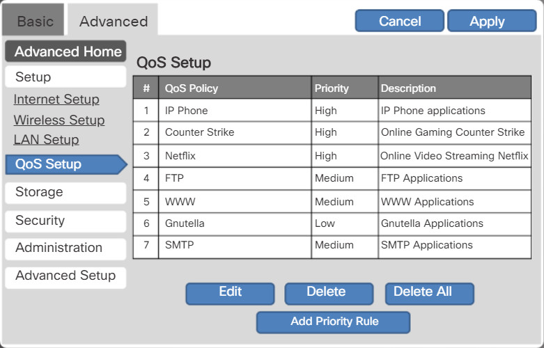
Typical Wireless Router QoS Interface
The figure is a simplified mockup of a QoS interface based on a Netgear GUI. You will usually find the QoS settings in the advanced menus. If you have a wireless router available, investigate the QoS settings. Sometimes, these might be listed under “bandwidth control” or something similar. Consult the wireless router’s documentation or search the internet for “qos settings” for your router’s make and model.
6.1.3.9 – Packet Tracer – Connect to a Wireless Network
In this activity, you will configure a wireless router and an access point to accept wireless clients and route IP packets.
Packet Tracer – Connect to a Wireless Network Instructions
Packet Tracer – Connect to a Wireless Network PKA
6.1.3.10 – Lab – Configure a Wireless Network
In this lab, you will configure basic settings on a wireless router and connect a PC to router wirelessly.
6.1.3.10 Lab – Configure a Wireless Network
6.1.4 – Firewall Settings
6.1.4.1 – Video Explanation – Firewall Settings
Click Play in the figure to view a demonstration of how to configure a firewall.
Click here to read the transcript of this video.
6.1.4.2 – UPnP
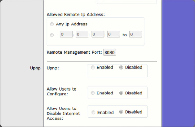
Universal Plug and Play (UPnP) is a protocol that enables devices to dynamically add themselves to a network without the need for user intervention or configuration. Although convenient, UPnP is not secure. The UPnP protocol has no method for authenticating devices. Therefore, it considers every device trustworthy. In addition, the UPnP protocol has numerous security vulnerabilities. For example, malware can use the UPnP protocol to redirect traffic to different IP addresses outside your network, potentially sending sensitive information to a hacker.
6.1.4.2 – UPnP
Many home and small office wireless routers have UPnP enabled by default. Therefore, check this configuration and disable it, as shown in the figure.
Search the internet for “vulnerability profiling tools” to determine if your wireless router is exposed to UPnP vulnerabilities.
6.1.4.3 – DMZ
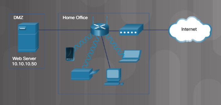
A demilitarized zone (DMZ) is a network that provides services to an untrusted network. An email, web, or FTP server is often placed into the DMZ so that the traffic using the server does not come inside the local network. This protects the internal network from attacks by this traffic but does not protect the servers in the DMZ in any way. It is common for a firewall to manage traffic to and from the DMZ.
Simple DMZ Scenario
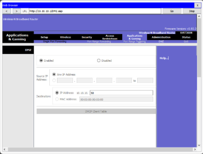
On a wireless router, you can create a DMZ for one device by forwarding all traffic ports from the internet to a specific IP address or MAC address. A server, game machine, or web camera can be in the DMZ so that the device can be accessed by anyone. For example, the Web Server in Figure 1 is in the DMZ and is statically assigned the IPv4 address 10.10.10.50. Figure 2 shows a typical configuration where any traffic sources from the internet will be redirected to the Web Server’s IPv4 address 10.10.10.50. However, the Web Server is exposed to attacks from hackers on the internet and should have firewall software installed.
DMZ Configuration Example
6.1.4.4 – Port Forwarding
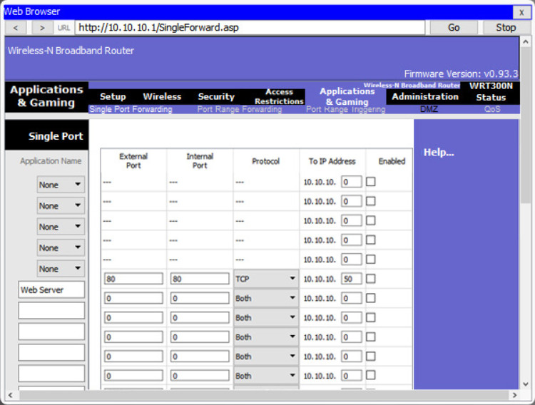
Hardware firewalls can be used to block TCP and UDP ports to prevent unauthorized access in and out of a LAN. However, there are situations when specific ports must be opened so that certain programs and applications can communicate with devices on different networks. Port forwarding is a rule-based method of directing traffic between devices on separate networks.
Port Forwarding to a Web Server
When traffic reaches the router, the router determines if the traffic should be forwarded to a certain device based on the port number found with the traffic. Port numbers are associated with specific services, such as FTP, HTTP, HTTPS, and POP3. The rules determine which traffic is sent on to the LAN. For example, a router might be configured to forward port 80, which is associated with HTTP. When the router receives a packet with the destination port of 80, the router forwards the traffic to the server inside the network that serves web pages. In the figure, port forwarding is enabled for port 80 and is associated with the web server at IPv4 address 10.10.10.50.
Port triggering allows the router to temporarily forward data through inbound ports to a specific device. You can use port triggering to forward data to a computer only when a designated port range is used to make an outbound request. For example, a video game might use ports 27000 to 27100 for connecting with other players. These are the trigger ports. A chat client might use port 56 for connecting the same players so that they can interact with each other. In this instance, if there is gaming traffic on an outbound port within the triggered port range, inbound chat traffic on port 56 is forwarded to the computer that is being used to play the video game and chat with friends. When the game is over and the triggered ports are no longer in use, port 56 is no longer allowed to send traffic of any type to this computer.
6.1.4.5 – MAC Address Filtering
MAC address filtering specifies exactly which device MAC addresses are allowed to or blocked from sending data on your network. Many wireless routers only give you the option of allowing or blocking MAC addresses, but not both. Technicians will typically configure allowed MAC addresses. The MAC address for your Windows computer can be found with the ipconfig /all command, as shown in Figure 1.
Laptop Addressing Information
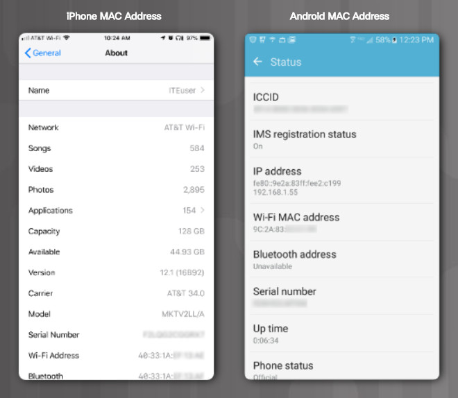
You may need to search the internet for where to find the MAC address on a specific device. Finding the MAC address is not always straight forward because not all devices call it a MAC address. Windows calls it a “Physical Address”, as shown in Figure 1. On an iPhone it is called the “Wi-Fi Address” and on an Android it is called “Wi-Fi MAC address”, as shown in Figure 2.
iPhone MAC Address and Android MAC Address
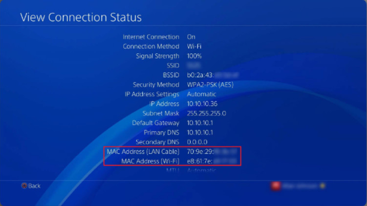
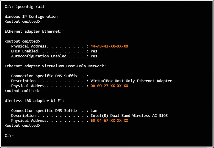
Additionally, your device may have two or more MAC addresses. For example, the PlayStation 4 in Figure 3 has two MAC addresses: one for wired networks and one for wireless networks. Similarly, a Windows PC might have multiple MAC addresses. As shown in Figure 4, the PC has three MAC addresses: wired, wireless, and virtual.
MAC Addresses on a PlayStation 4
Note: The last half of the MAC addresses and other identifying information is blurred out in Figures 2 and 3. The last six hexadecimal numbers are replaced with an X in Figure 4.
Multiple MAC Addresses on a Windows PC
Finally, consider the fact that new devices might be added to the network at any time. You can see how the technician responsible for manually configuring all these MAC addresses might be overwhelmed. Imagine having to manually enter and maintain dozens of MAC addresses in an interface such as the one shown in Figure 5.
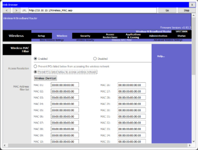
MAC Address Filter Configuration GUI
However, MAC address filtering may be your only option. Better solutions, such as port security, require purchasing a more expensive router or a separate firewall device, and are beyond the scope of this course.
6.1.4.6 – Whitelisting and Blacklisting
Whitelisting and blacklisting specify which IP addresses are allowed or denied on your network. Similar to MAC address filtering, you can manually configure specific IP addresses to allow or deny into your network. On a wireless router, this is typically done using an access list or access policy, as shown in the figure. Refer to your wireless router’s documentation for specific steps or search the internet for a tutorial.
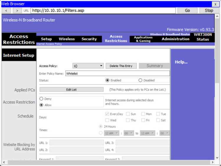
Whitelist Configuration
Whitelisting is a good tool for allowing your users, such as children or employees, access to those IP addresses you approve. You can also blacklist or explicitly block known sites. However, similar to MAC address filtering, this can become burdensome. Better solutions exist. Search the internet for “parental control software” and “content filters”.
6.1.4.7 – Packet Tracer – Configure Firewall Settings
In this Packet Tracer activity, you will configure a wireless router to rely on MAC filtering, allow access to a server in the DMZ, and disable the DMZ and configure support for Single Port Forwarding.
Packet Tracer – Configure Firewall Settings Instructions
Packet Tracer – Configure Firewall Settings PKA
6.1.4.8 – Lab – Configure Firewall Settings
In this lab, you will configure firewall settings to use MAC address filtering, a DMZ, and single port forwarding on a wireless router to manage connections and traffic through the wireless router.
6.1.4.8 Lab – Configure Firewall Settings
6.1.5 – IoT Device Configuration
6.1.5.1 – Internet of Things
6.1.5.1 – Internet of Things
The internet of today is significantly different than the internet of past decades. The internet of today is more than email, web pages, and file transfers between computers. The evolving internet is becoming an Internet of Things (IoT). No longer will the only devices accessing the internet be computers, tablets, and smartphones. The sensor-equipped, internet-ready devices of tomorrow will include everything from automobiles and biomedical devices, to household appliances and natural ecosystems.
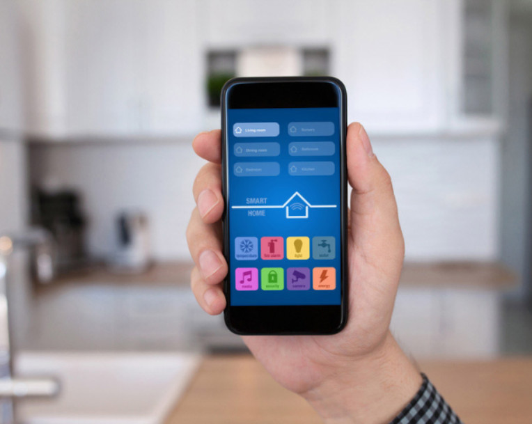
You may already have some IoT devices in your home. You can buy all kinds of connected devices including thermostats, light switches, security cameras, door locks, and voice-enabled digital assistants (such as Amazon Alexis and Google Home). These devices can all be connected to your network. In addition, many of them can be directly managed from a smartphone app, as shown in the figure.
6.1.5.2 – IoT Devices in Packet Tracer
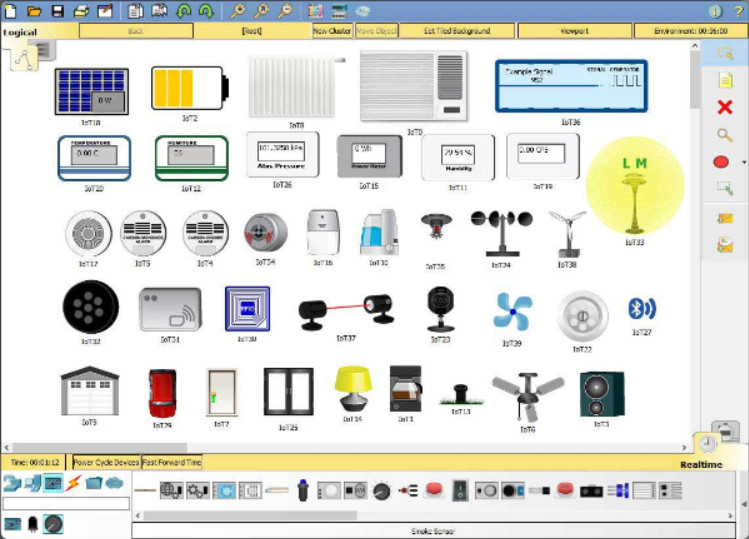
At this point in its infancy, the IoT market has not yet agreed upon a set of standards for IoT device installation and configuration. Configuring IoT devices is very much device specific. Consult the manufacturer’s documentation or website for configuration guides.
IoT Devices in Packet Tracer
In this course, you will use Packet Tracer to explore a basic IoT device configuration. The figure shows all the IoT devices in Packet Tracer. Packet Tracer also includes a number of sensors and actuators. In the figure, the sensors are shown in the bottom panel of the Packet Tracer interface.
6.1.5.3 – Packet Tracer – Control IoT Devices
In this activity, you have just installed various IoT devices around the house and wish to configure them as a home security system. You will configure the home gateway to use a motion sensor, test and reset security features, and set the air conditioning.
Packet Tracer – Control IoT Devices Instructions
Packet Tracer – Control IoT Devices PKA
6.2 – Basic Troubleshooting Process for Networks
6.2.1 – Applying the Troubleshooting Process to
6.2.1.1 – The Six Steps of the Troubleshooting Process

6.2.1.1 – The Six Steps of the Troubleshooting Process
6.2.1.2 – Applying the Troubleshooting Process to
Network problems can be simple or complex, and can result from a combination of hardware, software, and connectivity issues. As a technician, you should develop a logical and consistent method for diagnosing network problems by eliminating one problem at a time.
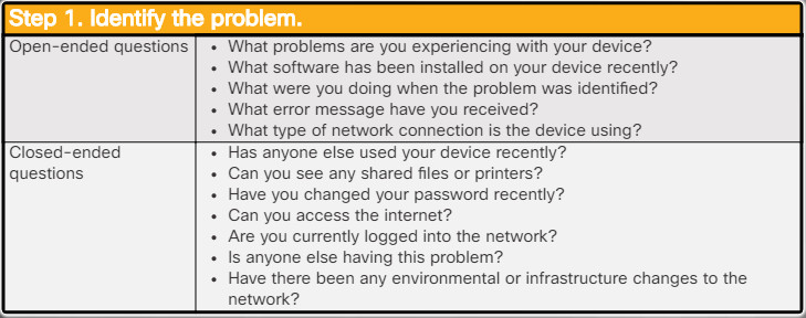
Identify the Problem
For example, to assess the problem determine how many devices are experiencing the problem. If there is a problem with one device, start with that device. If problem with all devices, start the troubleshooting process in the network room where all the devices are connected.
The first step in the troubleshooting process is to identify the problem. Use the list of open-ended and closed-ended questions in the figure as a starting point to gather information from the customer.
6.2.1.3 – Establish a Theory of Probable Cause
After you have talked to the customer, you can establish a theory of probable causes. The list in the figure provides some common probable causes for network problems.

6.2.1.3 – Establish a Theory of Probable Cause
6.2.1.4 – Test the Theory to Determine the Cause
After you have developed some theories about what is wrong, test your theories to determine the cause of the problem. Once the theory is confirmed, determine the next steps to resolve the problem. The list above shows some quick procedures that you can use to determine the exact cause of the problem or even correct the problem. If a quick procedure does correct the problem, you can then verify full system functionality. If a quick procedure does not correct the problem, you might need to research the problem further to establish the exact cause.

6.2.1.4 – Test the Theory to Determine the Cause
6.2.1.5 – Establish a Plan of Action to Resolve the Problem and Implement the Solution
After you have determined the exact cause of the problem, establish a plan of action to resolve the problem and implement the solution. The list in the figure shows some sources you can use to gather additional information to resolve an issue.

6.2.1.5 – Establish a Plan of Action to Resolve the Problem and Implement the Solution
6.2.1.6 – Verify Full Functionality and, If Applicable, Implement Preventive Measures
After you have corrected the problem, verify full functionality and, if applicable, implement preventive measures. The list in the figure shows a few steps to verify the solution.

6.2.1.6 – Verify Full Functionality and, If Applicable, Implement Preventive Measures
6.2.1.7 – Document Findings, Actions, and Outcomes
In the final step of the troubleshooting process, document your findings, actions, and outcomes, as shown in the list in the figure.

6.2.1.7 – Document Findings, Actions, and Outcomes
6.2.1.8 – Check Your Understanding – Network Troubleshooting Process
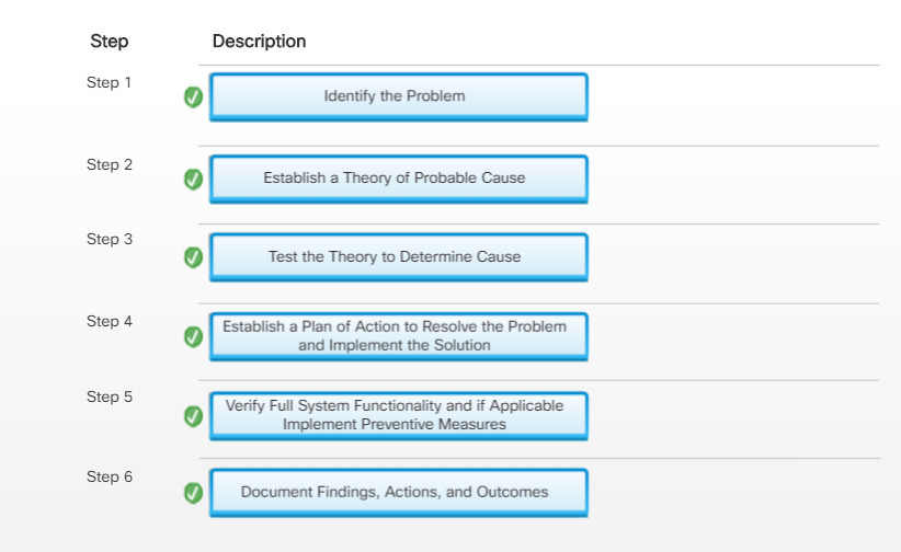
6.2.1.8 – Check Your Understanding – Network Troubleshooting Process
6.2.2 – Network Problems and Solutions
6.2.2.1 – Common Problems and Solutions for Networking
Instructions
Network problems can be attributed to hardware, software, or configuration issues, or to some combination of the three. You will resolve some types of network problems more often than others. Click a network problem to see probable causes and possible solutions. At any time, click another problem on the left side of the screen. To see a PDF of the entire table, click the Show PDF button on the lower right corner of the screen.
Identify the Problem
NIC LED lights are not lit.

User cannot use secured shell (SSH) to access a remote device.

Device cannot detect the wireless router.

Windows computer has an IPv4 address of 169.254.x.x.

Remote device does not respond to a ping request.

A user can access the local network but cannot access the internet.

The network is fully functional but the wireless device cannot connect to the network.

Local resources such as file shares or printers are unavailable.

6.2.2.2 – Advanced Problems and Solutions for Network Connections
Identify the Problem
A device can connect to a network device by the IP address but not by the host name.

The device does not obtain or renew the IP address on the network.

An IP address conflict message displays when connecting a new device to the network.

A device has network access but does not have internet access.

Users are experiencing slow transfer speeds, weak signal strength, intermittent connectivity on the wireless network.
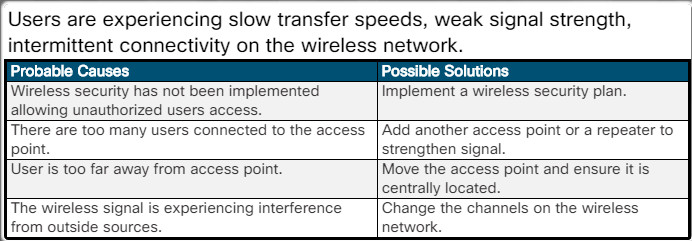
6.2.2.3 – Advanced Problems and Solutions for FTP and Secure Internet Connections
Identify the Problem
A user cannot access the FTP server.

A user cannot access the FTP server
The FTP client software cannot find the FTP server.

The FTP client software cannot find the FTP server
A device cannot access a specific HTTPS site.

A device cannot access a specific HTTPS site
6.2.2.4 – Advanced Problems and Solutions Using Network Tools
Identify the Problem
A device on one network cannot ping a device on another network.

A device on one network cannot ping a device on another network
The computer cannot Telnet into a remote computer.

The computer cannot Telnet into a remote computer
The nslookup command reports “Can’t find server name for address {ip-address}: timed out”, where ip-address can be any IP address.

The nslookup command reports “Can’t find server name for address {ip-address}: timed out”, where ip-address can be any IP address.
The ipconfig /release or ipconfig /renew command results in the following message: “No operation can be performed on the adapter while the media is disconnected.”

The ipconfig /release or ipconfig /renew command results in the following message: “No operation can be performed on the adapter while the media is disconnected.”
The ipconfig /release or ipconfig /renew command results in the following message: “The operation failed as no adapter is in the state permissible for this operation.”

The ipconfig /release or ipconfig /renew command results in the following message: “The operation failed as no adapter is in the state permissible for this operation.”
6.2.2.5 – Lab – Troubleshoot Network Problems
In this lab, you will diagnose the causes and solve the network problems.
6.2.2.5 Lab – Troubleshoot Network Problems
6.3 – Summary
6.3.1 – Conclusion
6.3.1.1 – Chapter 6: Applied Networking
In this chapter, you learned how to configure NICs, connect devices to a wireless router, and configure a wireless router for network connectivity. You also learned about firewalls, IoT devices, and network troubleshooting. You learned about the 48-bit MAC addresses that identified devices connected to an Ethernet LAN, and the two types of IP addresses, IPv4 and IPv6. IPv4 addresses are 32-bits in length and are written in dotted decimal format while IPv6 addresses are 128-bits in length and written in hexadecimal format.
Configuring an IP address on a device can be done manually or dynamically by using DHCP. You learned that manual, or static addressing, is appropriate for small networks while DHCP is best suited for larger networks. In addition to an IP address, DHCP can also automatically assign the subnet mask, default-gateway, and address of DNS servers. You configured a NIC to use DHCP on a Windows computer through a lab exercise. You were able to verify network configuration using the ipconfig /all command in Windows and test connectivity by using ping.
You then learned how to configure a wireless network including the configuration of a wireless router with basic wireless settings, NAT, firewall settings, and QoS. You then completed two labs one about configuring a wireless network and then a lab on configuring firewall settings. The wireless network lab had you configure basic wireless settings on a wireless host and an access point and then test connectivity. In the firewall lab you configured MAC filtering, a DMZ, and port forwarding.
The internet today is becoming more than just computers, tablets, and smartphones. It is becoming an IoT. These things are sensor-equipped, internet-ready devices that include automobiles, biomedical devices, household appliances, and natural ecosystems. You used Packet Tracer to explore IoT devices and their basic configuration.
At the end of the chapter, you learned the six steps in the troubleshooting process as they pertain to networks.

gracias por la informacion y guia